Thought I'd show off my new build

Lou C

Supreme Mariner
Joined
Nov 10, 2002
Messages
13,030
Everything looks absolutely great! When you get to the shift cable adjustment part, keep in mind you need the special tools to get an accurate adjustment, and because its a 2 cable system, you have to adjust the transom shift cable and the remote control cable. What are you doing to make the ESA work, with the electronic distributor?

for the tools and updated instructions...visit the Midnight Wolf OMC tools site.....
I have the original OMC tool set, which is for the shift rod height (you can do this with a straight edge and a ruler), the holder to hold the bellcrank in the pivot housing at 90* and the cable tool to set the length. Midnight sells the latter 2 tools, the shift rod one you can do without...
 

Efini Motorsport

Petty Officer 2nd Class
Joined
Feb 21, 2018
Messages
108
I've got a set of the adjuster jigs, just haven't had time to play with it and it's been raining the last few days. I've got a few ideas on the esa. Im interrupting the ground to the coil but I've got to try a few ways of doing it. If I'm lucky i can just use the stock interupt switch as my idle will be pretty low already. If not I'm going to make an esa with a fet and timer circuit that will drop the rpm as i shift. If i go that route I'm going to make it adjustable so i can drop the idle as low as i want to help shifting. I'm building it myself instead of buying it because no one makes an adjustable esa and it's about 1/10 the price to do it myself. Plus Went Overboard and all.
 

Lou C

Supreme Mariner
Joined
Nov 10, 2002
Messages
13,030
I can tell you that on the stock OMC ESA system it drops the idle to 450 rpm or so. That EFI engine can easily get that low I'm sure.
 

Efini Motorsport

Petty Officer 2nd Class
Joined
Feb 21, 2018
Messages
108
That's what I'm thinking. Stock idle should be around 500-550 anyway so I'm going to see if i can get away without an esa. Doubt I'm that lucky though
 

HT32BSX115

Supreme Mariner
Joined
Dec 8, 2005
Messages
10,083
The purpose of that ESA is to "pulse" the ignition and thereby "pulse" the torque on the "Dogs" It isn't just a one-time ignition interrupt like a Mercruiser.

With constant pressure to separate the dogs they separate during one of the torque low points (and it usually occurs within 1or 2 "pulses") in a properly adjusted lower shift cable, switches and associated linkage.....

While you might be able to pull them apart without the pulsing, it may take excessive "pressure".

I don't remember which (out of gear motion) places the lower shift cable into tension or pressure..... but the tension will probably not hurt a thing.

The "pressure" force OTOH, (pushing the cable) might eventually be more than it can withstand before bending the cable somewhere or stretching the cable housing (or both) .

And it may work several times before it causes a problem.

With the ESA working correctly, they work for years without problems.
 

Efini Motorsport

Petty Officer 2nd Class
Joined
Feb 21, 2018
Messages
108
Either way I'll be putting one in soon. I'm curious how far off i am with my current idle. My first shot is to just use the switch to interrupt coil ground as I'm shifting. I know doing it that way will possibly kill the engine as i go through the engagement point. If i held it at that point the engine would die
 

HT32BSX115

Supreme Mariner
Joined
Dec 8, 2005
Messages
10,083
Either way I'll be putting one in soon. I'm curious how far off i am with my current idle. My first shot is to just use the switch to interrupt coil ground as I'm shifting. I know doing it that way will possibly kill the engine as i go through the engagement point. If i held it at that point the engine would die
Well, if the drive quickly comes out of gear every time the ignition is interrupted and the shift plate quickly returns to center, the engine won't die.

But remember that OMC never did this and if I had to bet, they tried.

Because it would have been far cheaper to have a simple ignition interrupt (like Mercruiser) than have to design a complete system to provide multiple torque "low" pulses instead of just one.

Evidently they could not get the drive to come out of gear every time (with one pulse) and had to come up with a multiple-pulse system to guarantee coming out of gear everytime....... (Imagine the liability of a propulsion system that might not come out gear *sometimes* ....................Running into people and things by design, gives Company legal departments nightmares!!!)


In general, you probably want the lowest idle RPM that will allow shifting (out of gear) because the torque low(pulse) is "lowest" Also, you want it low so the into gear shifting is smooth. and you don't "bolt" ahead and scare everybody!

With your properly tuned EFI, you'll have not only full control over the idle RPM but probably far lower probability of the engine just dying during a single ignition interrupt event.

The whole process should just work better than with any carburetor!

I not sure the later EFI ECMs that OMC used had the pulsing algorithm built right in and they didn't use the separate ESA with EFI although they did have shift interrupt. (I cannot say for certain if the ECM pulsed ignition though.

The EFI drives were either early OMC "interim" Cone-Clutch or VP/OMC joint cone-clutch (SX ) drives. Which don't really need pulsing to get them out of gear. (The Mercruiser Bravo Cone-clutch drives don't use ignition interrupts at all.)
 

Lou C

Supreme Mariner
Joined
Nov 10, 2002
Messages
13,030
Interesting Rick, I recall I looking at a parts diagram for the OMC KC cone clutch and found out that they did use an ESA. Not sure why but I was surprised by it.
 

HT32BSX115

Supreme Mariner
Joined
Dec 8, 2005
Messages
10,083
Interesting Rick, I recall I looking at a parts diagram for the OMC KC cone clutch and found out that they did use an ESA. Not sure why but I was surprised by it.

I sure looked through a lot of the diagrams! Starting in 1990 model year (7.4L, 7.5L ), the "Interim" Cones have an "Interrupter" but no ESA. Makes me think they thought "Cones" needed only an ignition interrupt.

In 90, the the only Cones were the 7.4 & 7.5 The smaller engines (5.8L and smaller) were dogs.

Only saw ESAs on the Dog models....

In 91, the 7.4L got the cone (and interrupter) and 2 models of the 5.7 were cone and 2 were dogs. (only the dogs had the ESA) there was no 7.5L engine from 91 on.

In 92, the 8.2L, 7.4L, *some* 5.8L engine/drives were Interim Cone and had the interrupter.....the rest (of the 5.8L) were dogs (and had ESAs)

And so on.........

It's interesting to note however that an EFI model such as 58FAPRJVB 1993 had a dog clutch drive, and a shift plate (like earlier ones but no ESA. It must be built into the ECM firmware.....


I didn't look at all of them. But it was pretty consistent. The interim cones had an "interrupter" and no shift plate where all the dogs had shift plates and ESAs (except the EFI dogs)

The point here is that I didn't find ANY cone clutch drives with ESAs nor any Dogs with shift interrupters.

Now, in 1994 when some of them started seeing SX drives. (572AGPMDA 1994 for example) There's an item in the list of part diagrams called "ENGINE WIRE HARNESS & SHIFT MODULE"

but there's no shift module in the parts diagram or list. I think that might be a misprint. And there's no ESA to be found! If you find one, point it out. That would be interesting to see!

I also didn't see a shift interrupter on the SXs either.

Maybe someone who speaks Volvo can point that one out...

I am no expert and I definitely could have missed something!........

All I did was look at nearly all the sterndrive parts diagrams at http://epc.brp.com


Cheers,


Rick
 

Efini Motorsport

Petty Officer 2nd Class
Joined
Feb 21, 2018
Messages
108
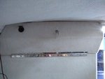
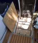
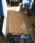
I'm so close i can almost taste it. I need a few more connectors and the wiring will be done. Then the dash and switch panel can get put back in. The last of the flooring, trim and bow ladder hatch are all in and look great. The engine seems to run great aside from the tach not working. I need to run a new wire straight from the coil instead of the computer. Shifting seems to be ok but I won't know for sure until I put it in the water on Friday. I still need to clean the interior and put the panels and seats back in. IMG_20190623_174537885.jpgIMG_20190623_174712276.jpgIMG_20190623_174653325.jpgIMG_20190623_135751071_HDR.jpgIMG_20190623_135909312.jpg
 

strokendiesel002

Petty Officer 1st Class
Joined
May 15, 2012
Messages
283
Hey that bow ladder is slick!

Everything is looking great! Can't wait to see a few full shots and the splash!
 

Efini Motorsport

Petty Officer 2nd Class
Joined
Feb 21, 2018
Messages
108
I'm thinking about making a combination cooler and sub box that fits under the ladder in that compartment
 

strokendiesel002

Petty Officer 1st Class
Joined
May 15, 2012
Messages
283
haha yea? How much room is under that ladder?!

I'm assuming the panel aft of the ladder and fore of the engine is your fuel tank, yes?
 

Efini Motorsport

Petty Officer 2nd Class
Joined
Feb 21, 2018
Messages
108
The rear compartment is the fuel tank. The front compartment is probably 10"h x 18"w x 24" l. Plenty of room for a shallow sub and decent size cooler. Or I'll do a big cooler and mount 2 8" subs under the backrest between the front and lounge seats
 

strokendiesel002

Petty Officer 1st Class
Joined
May 15, 2012
Messages
283
Built in full cooler with 2 8" subs under the backrest. I'd think they'd be less likely to get damaged by accident, along with having more effect at lower levels, no?
 

Efini Motorsport

Petty Officer 2nd Class
Joined
Feb 21, 2018
Messages
108
Bass is pretty Omni directional so I don't know there would be much difference between the two locations. The bigger difference would be the size speaker I could mount. Got to get in and take some measurements. I was going to do a cooler behind the helm seat and make a cushion for the top so I have another seat. I could do a cooler in the floor and just make another seat/storage. All of it may be more winter projects at this point.
 

Efini Motorsport

Petty Officer 2nd Class
Joined
Feb 21, 2018
Messages
108
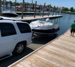
Pilots like to say any crash you can walk away from is a successful one. I think that any shakedown cruise where you can return to port under your own power is a good one. The first time out wasn't perfect but it certainly could have gone a lot worse. The first time the boat went in I found a few leaks. The biggest was in the exhaust because I didn't take into account how far the water came up inside the y pipe. Apparently just above the holes for the flappers. On of my flappers had fallen down into the Y pipe so I made new shafts for both with threaded rod run through the pipe and nuts on the outside. Got quite a leak on both sides. The bilge pump could keep up with it and would have done an even better job if there weren't two holes in the bilge hose. Some of what the pump pumped out just went into the bilge. We hauled the boat back out, pulled the flappers and sealed the holes as best we could. It was enough to be able to take the boat out anyway. To get out of the channel is a 20-30 min cruise all in a no wake zone.Engine temp and oil pressure were perfect and it ran great around 1200 rpm. Once I got out past the no wake zone I tried to accelerate but even with the throttle wide open (throttle body open all the way too) it wouldn't rev over 1400 rpm. The engine is in limp mode. We decided to just tool around the islands a little, take a dip then head back in. I won't be able to do anything on it until 'Monday but my first step is to get the OBD2 port working so I can scan the computer and see what's going on. Not sure if it's a sensor issue or programming issue.
I'm going to pull the manifolds and out drive so I can replace the bilge hose and check the lower shift cable adjustment. I got the cables to the point they'd shift but not near as easily as they should . I also got the parts in for version 1 and plan b of the shift interrupt so I can get those installed too. I need to get it all back together for the 4th so there will probably be some late nights this week. My girl took a few videos but this was the only picture. IMG_0922_01.jpg
 

Lou C

Supreme Mariner
Joined
Nov 10, 2002
Messages
13,030
You have Merc exhaust on yours if I recall, correct? The original set up on the flappers was with 2 grommets on the inside of the Y pipe and the pin that retains the flappers slides thru them then on both the bat wings I originally had and the later center riser exhaust I installed 2 years ago the rubber exhaust hoses slide down below the holes for the flappers so they don’t leak. If you can find the pins and grommets you can coat the holes on the outside with 3m 4200 to stop the leaks.
 
Top