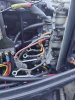
I have a Thunderbolt ignition, 398-9710A14, sitting atop a bit of a Franken-engine. I had to refit the flywheel magnets recently, and decided to check the coil resistance. Trouble is, when I look up that stator number at outboardignition.com it describes different wire colours to what I have.
I have the following:
- Red: 104 ohms to black
- Green: 3540 ohms to black
- Black
- Two yellows: no connection to any other wires. Less than 1 ohm between them.
Can anyone help me understand (1) what the various wires are, (2) whether these resistances are ok (they're fairly close to the listed ones in outboardignition.com but that's based on me assuming which wire is which - and I don't have anything to go by for the yellow ones), (3) if I remount the flywheel and spin it with the starter, what sort of voltages should I expect from the wires (and should I reconnect the wires to run that test, or leave them loose)?
Thanks in advance for the help!