Tilt/Trim backwards

GSPLures

Chief Petty Officer
Joined
Sep 3, 2019
Messages
564
How are you all doing today,

I have a 73' 140 mercruiser with mc-1 drive and the black prestolite pump.

I have the tilt/trim hooked up working and not leaking finally. I changed all the wire ends on the 3 button panel and pump side one at a time so I do not believe its a circuit issue. Although the boat was in horrible condition before I started restoring it so who knows if its right (I did refer to the schematics and didnt see anything wrong)

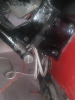
The hydraulic lines coming in from the transom are hooked up right I am assuming because with the lengths of the hoses they cannot go the other way.

Not sure if I have the hoses hooked up right on the outside though. (See picture, I am hoping its as easy as switching the lines)

Bottom button: trim goes up(also to trailering position)

Middle button: nothing

Top button: nothing

Middle/top together: drive goes down

I know there are some other issues as well because the buttons are not doing what it should. Im ok with having to hit 2 buttons at the same time but would like to at least have the top make it raise and the bottom make it lower.
 

Attachments

  • 20210718_162708_compress79.jpg
    20210718_162708_compress79.jpg
    1 MB · Views: 14

kenny nunez

Captain
Joined
Jun 20, 2017
Messages
3,331
Just remember, front line to the front port on the ram. The rams are not right and left, they are both the same.
The trim limit switch is mounted at the top of the gimbal ring which was designed to last about 1 month out of warranty. To replace it is a major repair job and not worth the effort. That is why you will have to push both buttons to trim/raise the drive.
 

MagKarl

Seaman Apprentice
Joined
Jan 18, 2021
Messages
47
Mine is plumbed as Kenny described. Front to front, back to back.
 

GSPLures

Chief Petty Officer
Joined
Sep 3, 2019
Messages
564
Just remember, front line to the front port on the ram. The rams are not right and left, they are both the same.
The trim limit switch is mounted at the top of the gimbal ring which was designed to last about 1 month out of warranty. To replace it is a major repair job and not worth the effort. That is why you will have to push both buttons to trim/raise the drive.
That is what I thought (when I bought the boat they were hooked up how i have them) it seemed backwards to me but I figured it was right since that's how I received it.

My gimbal ring was swapped with a newer one that has the hockey puck senders on the sides and those wires were all unhooked. I took a best guess at what bullet connector went to what.

Should I switch the way they are connected?

I have a trim sender at the top of my transom plate with a purple/white wire that is connected to the purple/white from the helm, and a black wire (covered in electrical tape assuming it is black) that is hooked up to a connector that goes to ground.

Then the hockey puck switches from the ring both have 1 bullet connector and the other wire cut. The harness going to the pump had 2 connections coming off of it so that is where I hooked those up. One going to a blue wire, the other to a solid purple wire.

I hope that makes sense, I know it is 2 different systems frankensteined to work. So there wasnt a schematic to give me a clue to what wire goes where.

I assume i am close because it is working and wont be backwards once I switch the hydraulic hoses.

I appreciate your help!
 

achris

More fish than mountain goat
Joined
May 19, 2004
Messages
27,468
That is what I thought (when I bought the boat they were hooked up how i have them) it seemed backwards to me but I figured it was right since that's how I received it.
Never assume the PO knew what he was doing (most don't).
My gimbal ring was swapped with a newer one that has the hockey puck senders on the sides and those wires were all unhooked. I took a best guess at what bullet connector went to what.
You should have 2 pairs of wires (just like the original system had). One pair is the gauge sender (and has absolutely no affect on how the system works), the other is the trim limit switch and only affects the pump when trimming UP.
Should I switch the way they are connected?
I have a trim sender at the top of my transom plate with a purple/white wire that is connected to the purple/white from the helm, and a black wire (covered in electrical tape assuming it is black) that is hooked up to a connector that goes to ground.
The purple/white is for the limit switch, not the sender, and (if the switch is working) should be hooked up to one (either, it doesn't matter which) of the black wires from the switch. The other black wire from the switch will connect to the blue/white wire that should be right next to the purple/white in the pump harness.
Then the hockey puck switches from the ring both have 1 bullet connector and the other wire cut.
Sounds like someone who was previously playing with the system didn't understand it. Cutting connectors off 🤦
The harness going to the pump had 2 connections coming off of it so that is where I hooked those up. One going to a blue wire, the other to a solid purple wire.
They should be hooked to the trim limit switch.
I hope that makes sense, I know it is 2 different systems frankensteined to work. So there wasnt a schematic to give me a clue to what wire goes where.

I assume i am close because it is working and wont be backwards once I switch the hydraulic hoses.
Yes, you need to get the hoses swapped.

Here's the best I can do for you as far as a diagram based on what I have read. (your 1973 engine harness may not have a wire for the gauge sender, so you'll need to run one (or you may already have) to the helm for the gauge to work.) Also, read THIS post. It explains how the buttons are designed to work.

1Sol-trim.PNG
 
Last edited:

GSPLures

Chief Petty Officer
Joined
Sep 3, 2019
Messages
564
Never assume the PO knew what he was doing (most don't).

You should have 2 pairs of wires (just like the original system had). One pair is the gauge sender (and has absolutely no affect on how the system works), the other is the trim limit switch and only affects the pump when trimming UP.

The purple/white is for the limit switch, not the sender, and (if the switch is working) should be hooked up to one (either, it doesn't matter which) of the black wires from the switch. The other black wire from the switch will connect to the blue/white wire that should be right next to the purple/white in the pump harness.

Sounds like someone who was previously playing with the system didn't understand it. Cutting connectors off 🤦

They should be hooked to the trim limit switch.

Yes, you need to get the hoses swapped.

Here's the best I can do for you as far as a diagram based on what I have read. (your 1973 engine harness may not have a wire for the gauge sender, so you'll need to run one (or you may already have) to the helm for the gauge to work.) Also, read THIS post. It explains how the buttons are designed to work.

View attachment 345752

Thank you,

I knew I should have trusted myself and not how it was, I rebuilt the motor harness for the same reason (lots of wire nuts for connections)

You are correct I was wrong when I said trim sender I looked up the parts diagram it is the reverse lock valve that is on the transom plate.

I have the purple/white wire (from helm looks like it was ran at some point by the PO)connected to the purple/white wire coming off of the assembly. The other wire from the assembly going to a connector to ground (I know its a ground that's where my bilge,blower, and nav light get a ground from in a splice)

Which if that is correct (wasn't sure), and from the diagram does not appear to be leaves only 2 more connections (assuming that is why the others were cut).

So based off of that diagram I should put a new end on the limit switch and connect that to the purple and blue wires coming out of the harness that is connected to the pump.

I have to trace the purple/white wire back if it goes to the gauge connect that to the sender and run the 2nd wire and replace the connector and hook that also up to the sender(missing as far as I can tell have not seen one).

Where are the wires from the reverse lock valve supposed to go? It is a purple/white and a unknown color (wrapped in electrical tape). The ground has a bullet connector spliced in is why I connected it there but then that leaves the purple/white wire with nowhere to go.

I appreciate your help, you have me going in the right direction now.
 

GSPLures

Chief Petty Officer
Joined
Sep 3, 2019
Messages
564
Well I did a lot of research and I have everything finally hooked up correctly. Not sure if the limit switch works just yet I need to buy some bullet connectors for the cut wires. I jumped it in the harness so I do not have to press both buttons to raise the drive.

The trim gauge shows the drive pegged out in the up position so I am going to go through the calibration procedures in the manual.

Since I have the old sensor on the transom plate and also the new style on the outside of the gimbal ring can I use either one?
 

kenny nunez

Captain
Joined
Jun 20, 2017
Messages
3,331
If the original hydraulic one still works just keep using it until it quits then start using the “ear muff” one.
 

GSPLures

Chief Petty Officer
Joined
Sep 3, 2019
Messages
564
If the original hydraulic one still works just keep using it until it quits then start using the “ear muff” one.
Worst case scenario I am going to run with out the limit or gauge for now. I know its not ideal but I should be the only one driving the boat (but will make a warning sticker just in case).

Eventually I will purchase a newer style pump and replace the newer style sensors and get rid of all the extra junk on the transom plate.

Since this boat was an entire gut and rebuild I am trying to put the money where it will be the most beneficial for now. I am almost ready for a splash fingers crossed next week.
 
Top