Troubleshooting Trim Gauge/Sender

hoowahfun

Petty Officer 2nd Class
Joined
Sep 1, 2016
Messages
186
hi everyone. I installed a new trim sending unit and limit switch this weekend with new wiring through the transom housing and hooked everything up. I turned the key to the “On” position, and the trim gauge just stays pegged all the way up. It stays that way whether key is on or off with no movement. It was like this before I swapped sensors, but the sensors were also bad because the contacts were corroded away inside when I took them apart.

I know a lot of people say they just leave them broken and operate by feel, but I’m not sure I’ve got the experience necessary for that so would rather have the gauge working for reference.

How would I go about troubleshooting to determine if it’s a bad gauge or bad wire somewhere between the gauge and the new wires from the sensors? All I have is a cheap digital multimeter. Thanks!

Edits: spelling wrror
 
Last edited:

Bt Doctur

Supreme Mariner
Joined
Aug 29, 2004
Messages
19,344
go to the rear of the gauge and remove the sender wire, gauge should go down. If No, gauge may be defective.If Yes, wiring is grounded somneplace
 

hoowahfun

Petty Officer 2nd Class
Joined
Sep 1, 2016
Messages
186
Is that the brown wire? Maybe it was brown/White can’t recall.
 

harringtondav

Commander
Joined
May 26, 2018
Messages
2,440
It's also possible you installed the sender one or more spline teeth out of position with the pivot pin splines.
Trim full down.
Loosen the sender hsg. and rotate it full clockwise in the slot, If the gage won't come off of full up......
Remove the clamp screws and continue to rotate the sender clockwise until your gage moves to full down.
Then pull the sender out of the splines, and rotate it counter clockwise until the screw holes in the gimbal ring line up with the slots and reinsert it in the closest spline.
Start the screws and clamps, but keep them loose.
Trim up until the motor stops.
Rotate the sender until the gage is at 3:00 o'clock and clamp it tight.
Recheck. Full down should be at 6:00 o'clock, Up at 3:00 o'clock, trailer above that.
 

wellcraft-classic210

Master Chief Petty Officer
Joined
Sep 22, 2010
Messages
839
Your gauge will peg when the signal wire sees low or no resistance ( more current ) and will go low when the resistance is high ( less current ) on a system that's operating correctly.

This can be easily tested & seen when disconnecting the signal wire going to the sensor ( creating an open / high resistance ) then grounding ( creating a short / low resistance ) -- I good place to do that is at the sensor to harness connection which is commonly near your main breaker because it tests your wiring and the gauge at the same time.

If that's working well try adjusting the trim sensor position on the outdrive as stated above // it may need to be rotated to the proper position .
 

tank1949

Lieutenant Commander
Joined
Apr 4, 2013
Messages
1,911
hi everyone. I installed a new trim sending unit and limit switch this weekend with new wiring through the transom housing and hooked everything up. I turned the key to the “On” position, and the trim gauge just stays pegged all the way up. It stays that way whether key is on or off with no movement. It was like this before I swapped sensors, but the sensors were also bad because the contacts were corroded away inside when I took them apart.

I know a lot of people say they just leave them broken and operate by feel, but I’m not sure I’ve got the experience necessary for that so would rather have the gauge working for reference.

How would I go about troubleshooting to determine if it’s a bad gauge or bad wire somewhere between the gauge and the new wires from the sensors? All I have is a cheap digital multimeter. Thanks!

Edits: spelling wrror

No disrespect, but you have to adjust both. Get a buddy to rotate sender while you watch gauge needle. If nothing, u have a dead ground somewhere. Sender is nothing but a reho-stat. Test limit switch using a buddy too to raise and lower OD. Black paint on your trim rams should be a good base line for initial setting . Be sure to have a good charged battery. Limit switch is ether off or on. Good luck.
 

hoowahfun

Petty Officer 2nd Class
Joined
Sep 1, 2016
Messages
186
No disrespect, but you have to adjust both. Get a buddy to rotate sender while you watch gauge needle. If nothing, u have a dead ground somewhere. Sender is nothing but a reho-stat. Test limit switch using a buddy too to raise and lower OD. Black paint on your trim rams should be a good base line for initial setting . Be sure to have a good charged battery. Limit switch is ether off or on. Good luck.

Agreed. I started with the position sensor first since it seemed pointless to go to the limit switch if the position wasn't reading accurately. Hope to get to it this weak if the weather cooperates.
 

hoowahfun

Petty Officer 2nd Class
Joined
Sep 1, 2016
Messages
186
I replaced my trim limit and trim level sensors on my alpha 1 3.7 MerCruiser and fighting same problem. I bought a $10 multimeter on the internet and set the sensor for zero or 10 ohms when the drive is full down, but need to do more refinements. The trim level gage I also replaced. All the parts I replaced are from sierra. Most often the wires from the senders fail and pain to replace. I had to remove all the boots to reach the 7/16 bolts using 70 degree offset wrench, but a 20 degree offset I think will work. buying offset wrench and cut so wrench can pass the u joint boss and heat using welding touch to bend to get the right angle helps. I had to pay a MerCruiser shop to get everything back together and they still couldn't get sensors adjusted, but at least my sensor wires and all the boots are new. I also discovered the factory wire connectors like to pop loose so check the electrical connections first. My fails are posted to my you tube channel that you can find by query on MerCruiser 3.7 subject or alpha 1 sensor replacement videos. I hope this information helps

Yeah I had to pull the drive and the boots as well, and had an old 7/16 wrench laying around that I heated and bent until I got the right angle to get at the top bolt. Was a huge pain. I tried getting the top bolt with a 1/4 extension and socket on a swivel, but it wouldn't fit. Even if it did, I don't know how I would of been able to get it back in without taking everything apart.
 

hoowahfun

Petty Officer 2nd Class
Joined
Sep 1, 2016
Messages
186
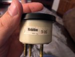
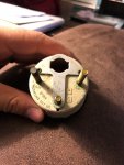
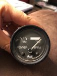
Okay so I pulled the wires off and the gauge didn't move. I pulled the gauge out, is there any way to bench test this thing? Maybe the needle position is where it's supposed to be if it's not getting any signal at all?
 

Attachments

  • photo296926.jpg
    photo296926.jpg
    532.2 KB · Views: 3
  • photo296927.jpg
    photo296927.jpg
    757.5 KB · Views: 3
  • photo296928.jpg
    photo296928.jpg
    573.6 KB · Views: 3

achris

More fish than mountain goat
Joined
May 19, 2004
Messages
27,468
Position sender for the gauge and the limit switch are completely separate. No need for one to be working for the other to work. The position sender (on the starboard side of the drive) is only connected to the gauge, nothing else. The limit switch connects to the pump harness.

The best way to test the gauge is to put power on it with the sender disconnected. The needle should show full down. Grounding the S terminal should peg the gage full up.

With your multimeter, check the resistance of the sender. It should swing between 240 ohms (full down position) and about 33 ohms (full up position). If it doesn't, you need to reorient the sender.

Chris. .....
 

hoowahfun

Petty Officer 2nd Class
Joined
Sep 1, 2016
Messages
186
Okay not sure I did this right, electricity is not my strong suite.....12V battery with negative to S terminal and positive to P, gauge goes down/left to 2nd tick mark from the last. Negative to G and positive to P, gauge pegs full right/up (I’m assuming left is down and right is up). Was a little confused on reading ohms on the sender...guess I’ll have to try that back at the boat tomorrow evening when I have some light.

If anything i think this tells me the gaige is at least partly functional. Not sure why it didn’t peg full left.

just tried something: negative to P and positive to G pegs the gauge full left if I jiggle it a bit. Not sure what that means. Sticky gauge maybe?
 

achris

More fish than mountain goat
Joined
May 19, 2004
Messages
27,468
You should have 3 terminals on the back, P = Power (this you connect to battery positive), G = ground (connect this to the negative of the battery). The third terminal is S, to be connected to the sender. Only ever, and always, connect the P to +12v, the G to the negative. When I say 'ground the S terminal', that means, once the positive and negative are connected.

Connecting positive to the 'G' and negative to the 'P' will destroy the gauge.

Chris.........
 

hoowahfun

Petty Officer 2nd Class
Joined
Sep 1, 2016
Messages
186
Hopefully I didn’t fry it during my “testing”. Will put it back in this evening hopefully and play around with the sender some more and also try to ground it out as you suggested to see what happens.

Just to clarify, when you say ground out the S terminal, that means jumper the S to the G with negative on G and positive on P (with sender disconnected)?

Thanks for your help.
 

wellcraft-classic210

Master Chief Petty Officer
Joined
Sep 22, 2010
Messages
839
uswebdev -- You should really start your own post -- // That said -- If your trim sensor and limit switches need to be replaced that should to be done while the bellows is being serviced for access to the necessary components // you can run without them but they do help most people to have better control.
 

hoowahfun

Petty Officer 2nd Class
Joined
Sep 1, 2016
Messages
186
Okay I think I figured out what’s going on. Put the gauge back in then with the key in the On position started to slowly turn the sending unit. This time I saw movement, but it would only go about halfway across the gauge then stop, then as I kept turning it would jump back up to full up. I put it back to where it would go the farthest left it would go then tapped on the gauge and it kept going down until it was almost all the way down.

Then I went back to the sender and proceeded to turn it and the gauge went to the middle and just got stuck there regardless of how far I turned the sender. That indicates to me the gauge is just sticky and probably no good. Is there a way to “unstick” a gauge like this or just better to replace it?
 

tank1949

Lieutenant Commander
Joined
Apr 4, 2013
Messages
1,911
Okay not sure I did this right, electricity is not my strong suite.....12V battery with negative to S terminal and positive to P, gauge goes down/left to 2nd tick mark from the last. Negative to G and positive to P, gauge pegs full right/up (I’m assuming left is down and right is up). Was a little confused on reading ohms on the sender...guess I’ll have to try that back at the boat tomorrow evening when I have some light.

If anything i think this tells me the gaige is at least partly functional. Not sure why it didn’t peg full left.

just tried something: negative to P and positive to G pegs the gauge full left if I jiggle it a bit. Not sure what that means. Sticky gauge maybe?

I suspect that it is pegging because power from gauge is going to ground. U should get a hand full of jumper leads and pull gauge and wire directly to your new senders with jumper leads. Take all the other stuff out of the equation. Down load the MC manual on wiring. Most show color codes of wires and proper connections to the back of gauge for your hot leads. I have replaced several gauges and senders. I am pulling one of my bravo transom assemblies tomorrow to later replace transom. When out, I will also replace both senders on gimbal ring. There is a video of a man drilling holes in his MC transom assembly and boat above the water line to reroute new sender wiring. Thus bypassing MC's poor design of having to "fish" wires through the top part of ASSEMBLY... If I wasn't removing complete assembly, I'd do that. Good luck!
 

wellcraft-classic210

Master Chief Petty Officer
Joined
Sep 22, 2010
Messages
839
If your saying the needle stays stays pegged or 1/2 way and does not go down with the following condition;

-signal wire disconnected at the gauge ( and not other wires touching that connection )
-12 volts applied to gauge
-a good ground applied to the gauge

that does sound like the Gauge is suspect -- possible internal damage

Just curious -- what happens when the signal pin is grounded during the above condition -- does the needle move ?
 

hoowahfun

Petty Officer 2nd Class
Joined
Sep 1, 2016
Messages
186
If your saying the needle stays stays pegged or 1/2 way and does not go down with the following condition;

-signal wire disconnected at the gauge ( and not other wires touching that connection )
-12 volts applied to gauge
-a good ground applied to the gauge

that does sound like the Gauge is suspect -- possible internal damage

Just curious -- what happens when the signal pin is grounded during the above condition -- does the needle move ?

Before I took the gauge out, it would stay pegged full up. However, I misunderstood the part about grounding out the sender so I didn't test it that way and will tonight if i get the chance. I'll take the sender wire off the gauge, see if it goes down, then jumper the S terminal to the G terminal and see what happens.

The gauge got stuck half way when I was messing around with the sending unit last night after I put the gauge back in and wired it up. I finally got movement, but would stop at the half way mark on it's way down and just stop. I tapped on the gauge and it went almost all the way down, but couldn't get it to move much after that and it was stuck half way when I stopped last night.

I also need to check the Ohms like achris described earlier.

I'm hoping to revisit this later tonight or tomorrow evening and also hopefully get the trim limit switch set properly. I'm planning to have my first time out on the lake with this thing Saturday so I at least want to have the limit switch working so I don't go too far up. The gauge would be a bonus at this point.
 

wellcraft-classic210

Master Chief Petty Officer
Joined
Sep 22, 2010
Messages
839
Great opportunity to get used to using a dvm

--Try checking dc voltage on the 12v+ terminal and using the ohm meter between that disconnected signal wire and ground to get the R value as mentioned above.

And hoping you don't mind an added fyi

---Normally touching wires to GND is not recommended as it will likely cause a short circuit / spark and take out a fuse unless its a gnd wire or the power is off -- In this case the gauge has some internal resistance to prevent that.

---Ohm meter checks are to be done only on ckts with no other electrical power applied such as Battery or alternator

---DVM Voltage checks are with power on and in DC for almost all vehicles // don't confuse that with the ac power setting used for houses etc
 

hoowahfun

Petty Officer 2nd Class
Joined
Sep 1, 2016
Messages
186
Great opportunity to get used to using a dvm

--Try checking dc voltage on the 12v+ terminal and using the ohm meter between that disconnected signal wire and ground to get the R value as mentioned above.

And hoping you don't mind an added fyi

---Normally touching wires to GND is not recommended as it will likely cause a short circuit / spark and take out a fuse unless its a gnd wire or the power is off -- In this case the gauge has some internal resistance to prevent that.

---Ohm meter checks are to be done only on ckts with no other electrical power applied such as Battery or alternator

---DVM Voltage checks are with power on and in DC for almost all vehicles // don't confuse that with the ac power setting used for houses etc

No, I don't mind at all. Never hurts to learn something new or be reminded of something I already know :)

Okay so updated test results:

1. The position sensor is installed with index marks lined up and screw hole about center of the slot. Should be close. Sender connected to gauge.
2. Power ON.
3. Trim full UP, 885 Ohms between S and G terminals.
4. Trim full DOWN, 1012 Ohms between S and G terminals.
5. Numbers not what I expected, check the site on my phone to see power should be OFF. Doh!
6. Power OFF.
7. Trim full UP, 36 Ohms between S and G. Gauge reads up position.
8. Trim full DOWN, 2 Ohms between S and G. Gauge in same position.
9. If I tap on the gauge when it is either full UP or DOWN, the gauge will move in the direction it's supposed to, but requires a lot of tapping.

I realized after I had covered the boat back up and come in for the night that I forgot to check the voltage on the back of the gauge. Will do that tomorrow if I need to. Should also disconnect sender again at gauge and test Ohms between G terminal on gauge and sender wire to see what the Ohms are. Seems like that should tell me if the sender/wiring is good.

One success tonight, I did get the limit switch set up properly so I'm relieved about that!
 
Top