Wanted --- Bad late model CDM trigger assembly---

Redbarron%%

Chief Petty Officer
Joined
Dec 7, 2017
Messages
479
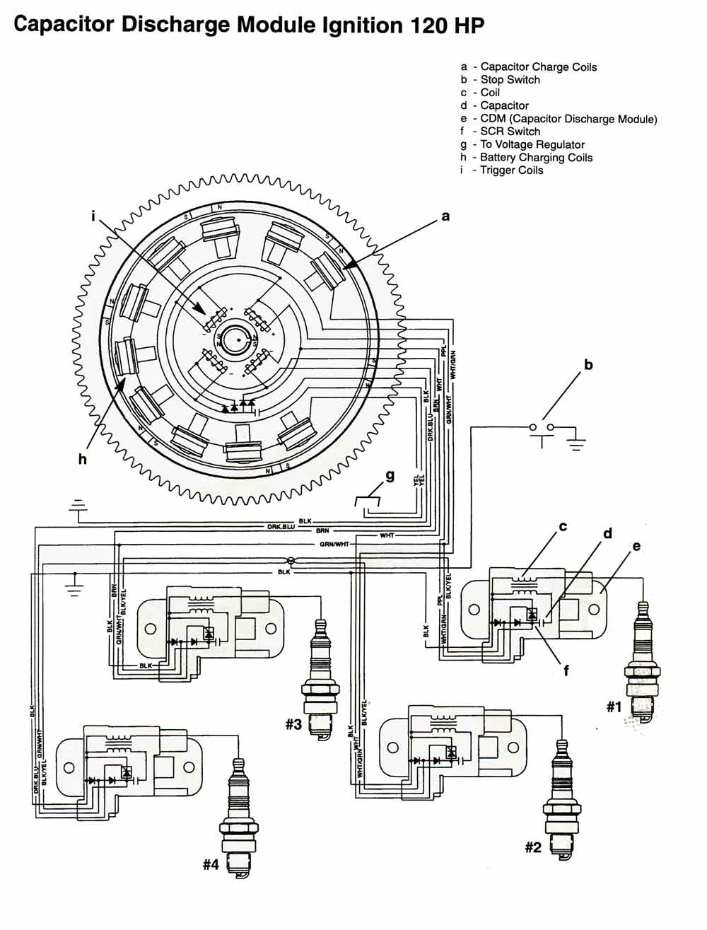
120HP_96_up._CD.jpg
With regard to 3, 4, or 5 cylinder trigger for the Force/Mercury CDM engines. I need to dig out the bias circuit to be able to make an external bias circuit to upgrade the CDI to the CDM modules. I have looked all over for the internal circuit without success.
The CDM modules are cheap on eBay especially the 200 hp Mercurys. The harnesses are also easy to come by, but I worry about the bias as applied to these modules.
If I figure this out you can retain the old flywheel and trigger, but upgrade to the CDM.
I found this drawing of the CDM system and it shows diodes and a capacitor return to ground and all I need now is to know if this is correct and the value of the capacitor and it's voltage rating.
 
Last edited by a moderator:

Redbarron%%

Chief Petty Officer
Joined
Dec 7, 2017
Messages
479
I found this write up on the bias circuit in the trigger A positive voltage pulse (N–S) will activate the electronic switch (SCR) inside the capacitor discharge module (CDM). The switch discharges
the capacitor voltage through the coil primary
windings. The return voltage pulse exits the
CDM through the ground wire and returns
through the trigger ground. Once inside the trigger the voltage will supply the bias capacitor with
a negative charge. For the next trigger in sequence to activate its CDM (SCR), the positive
trigger voltage must first over come this offset
bias capacitor voltage. The delay produced by
having to over come this offset bias capacitor
voltage prevents the timing from electronically
advancing as engine speed increases. I need to find out the value of the cap to get the bias correct for the CDM modules.
 
Last edited by a moderator:

jbcurt00

Moderator
Staff member
Joined
Oct 25, 2011
Messages
25,109
Red, please remember Solicitation isnt permitted

There is no used parts wanted, for sale or swap section @ iboats forums.
 

Redbarron%%

Chief Petty Officer
Joined
Dec 7, 2017
Messages
479
Bought one off eBay that should be good, but may be bad. I also found a late model flywheel that should work with tine CDMs and make a complete setup.
I am a little disappointed because I had hoped to be able to get the CDMs working properly without having to change the trigger and flywheel at a pretty high cost.
If you had to buy a new flywheel it would be over $500 and the trigger the best part of a C note.
If the trigger I bought is defective I will dig into it to determine how it is made and post that after I have had a chance to test it.
Until then the CDMs will work with the old style push - pull coils, but the advance due to lack of bias is too great.
 
Last edited by a moderator:

Redbarron%%

Chief Petty Officer
Joined
Dec 7, 2017
Messages
479
I AM NOT BIASED.....

For an update on my continuing project.
I ordered off eBay a CDM trigger coil and late flywheel for the CDM engine and discovered that there is a change in crankshaft and flywheel with the CDM as well and the new flywheel has a larger taper than the 1995 CDI.....

So back to the conversion process. I am cutting open the CDM trigger coil.
My plan now is to determine the circuitry and build a small interface board to receive the trigger coil and White /Black wires and then condition them and plug from there into the CDM harness. I think I will build the interface for 4 or 5 cylinders so that any engine from 2 to 5 cylinders can be updated to CDM ignition and use all of those CDM modules that are on the used market.
Bias, bias, wherefore art thou, bias.
 
Last edited by a moderator:

Redbarron%%

Chief Petty Officer
Joined
Dec 7, 2017
Messages
479
OK I am ready to be biased! I got the potting cleaned out and the circuitry drawn out and I think I have figured out how to test using the circuit board that is built in the trigger coil.
After I have tested the operation and how well the bias maintains the timing with the rpm increasing I will make a breadboard that I can wire in between the early push pull trigger coil and the CDMs to add the negative bias. It may be a few days or weeks to get it tested and wrung out.
 

Redbarron%%

Chief Petty Officer
Joined
Dec 7, 2017
Messages
479
Here is an update on the bias circuit project. I got the potting material dug out of the trigger coil I had and traced the circuitry and figured out what was going on. To test to see if the basic circuit was working I reinstalled the old trigger and wired the circuit board up to go between the trigger and the CMD harness, taking into account the need for different grounding etc.
To make a long story short the thing works with a stable output and the timing seems to be correct at least running in the driveway on the hose. The only way to tell for sure is to put it in the water and run it WOT and check the timing there and at idle.
My plan is to replicate the circuit building it on a small piece of perfboard and then test that. Also I need to check the output pulses with an oscilloscope to make sure that the pulse to the CDMs of reliably over 0.6 vdc + and does not vary with RPM. It is possible that I will have to fine tune the values of the resistors and capacitors for the difference in the coil and magnet arrangements in the two systems.
Bias is important, good in this circuit, not good in other places and conditions.
 

Nordin

Commander
Joined
Jun 12, 2010
Messages
2,588
Redbarron nice to see someone digging in to the electronics.
May I ask you how do you clean out the potting in the CD units?
I am thinking to repair other CD units from Chrysler/Force and even other brands but to clean out the potter is a PIA.
Do you use some kind of solvent and if which do you use?
 

Redbarron%%

Chief Petty Officer
Joined
Dec 7, 2017
Messages
479
I used some heat from a focused heat gun (small outlet, high temp) and pried with various small sharp, pointed, flat, dull, and various picks.
I haven't figured out what kind of solvent that will dissolve it and there are several types of potting material used, some soft and pliable and some hard.
I think that this project might be useful in upgrading these old motors to improve the reliability. The main difference in the older and the XR (Extreme Reliability) is basically the electronics.
I was bale to buy the 200 HP CDM modules and harness at a very reasonable price on eBay and the only problem has been the proper bias.
I think I had a bad flywheel trigger magnet that had a weak output that kinda worked with the CDMs. Changing the flywheel due to loose magnets caused the timing to advance beyond what could be adjusted indicating the need for the bias circuit.
More testing needs to be done and I hope to get the boat in the water in the next day or so.
Thanks for the response, Nordin.

J.D.
 

Redbarron%%

Chief Petty Officer
Joined
Dec 7, 2017
Messages
479
Today's update.
OK yesterday I went out in the morning to test start the Frankenforce ignition and no start, no spark. I took the adapter out and the ignition did spark, but of course the timing was off. I fiddled, resoldered connections etc and later it would start every time.
This morning I went out first thing and the same ting, but I decided that instead of removing the adapter I would try jumping the white / black common wire to ground and bypass that part of the circuit. Spark and cranked right up, but of course the timing was off, but also of course the timing came right back after I unclipped the jumper.
I am thinking that perhaps fine tuning the circuit values might get that initial pulse over the 0.6 DVC to fire the CDM modules or perhaps add a reed relay that in turned on by the starter to by pass that part of the circuit for starting. I hate to add more complexity, but if it works ....
Thinking more about the circuit design and how to work this problem.
Undoubtedly the early push - pull coils have lower voltage output than the later single ended CDM trigger coils.
At idle the capacitor charges to around -8 DVC and the wires going to the CDM modules is around - 5 VDC.
Once the engine is running the coild are generating enough voltage to fire the CDM, but not quite at cranking speed, I assume.
One almost wishes for a system like the old battery ignition that would generate a spark no matter the speed.
It looks like I need to get the Oscilloscope out like I have threatened to actually see what the levels are.
 
Last edited:
Top