What a mess I have!!! will need total rewiring.

msargius

Seaman
Joined
Mar 28, 2010
Messages
61
I started by first fixing a water leak in my new boat, and got it fixed...Now I turn to everything around me. My next step to check the electrical wiring. Some instruments don't work, the fuse holders are warm from corrosion and loose connections, some switches been disconnected as well as the fuses. Wires jacked cracked, dry roted, and fried along some of the wires, none insulated splices next to each other by the engine, you name it I can proudly say (not) I have it. Although I love electric work and electronics, I am kind of clueless when it comes to engine wiring etc... So this is a learning experience for me but I can understand the terminologies and some calculations from my experience in electronics and also high voltage work.

I definitely need to rewire this boat from a-z. I looked at the diagrams you have posted, but I still need help trying to restore this boat to the original specs with some improvements.

I am not sure if the boat was rewired before, but whoever was doing it disconnected to many things. Well To start things off I was wondering if previous people who rewired their boats have the AWG of the engine cables used handy (this will speed things for me as I don't have to redo the calculation or to check every wire for its thickness (engine wiring) i.e. tach, amp, oil, water, etc.... what I have are spliced in so many areas and joined with different wire AWG in between.

I have two questions for now

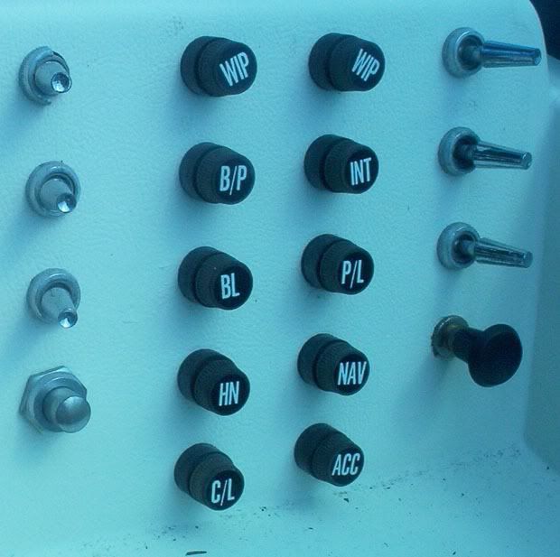
1. What are the letters on the fuses short for?

WIP = Wiper
B/P = Bilge Pump?
BL = Blower
HN = Horn
C/L = Cockpit Light - Cigarette Lighter (Thanks to Rick)
INT = Interior
P/L = ? Panel Light (Thanks to Rick)
NAV = Navigation
ACC = Accessories.


fuses.jpg


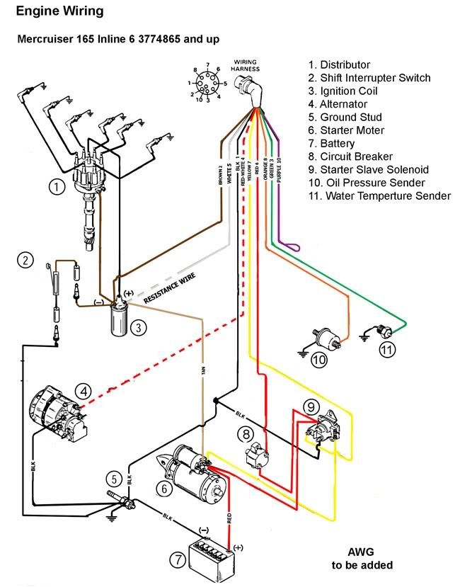
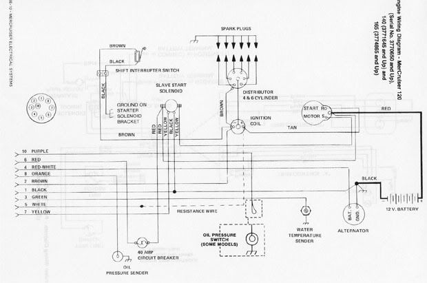
2. Engine and tach wiring.
Below you will find the original engine wiring. My tach is not working. so tracing the wiring I discovered that some connections are reversed on the ignition coil. Wires that come from the start motor and the white wire (tach sender) are connected to the negative side of the ignition coil. The shift interrupt and brown from harness is connected on the positive side. Also the brown wire coming from Distributor is connected to the positive on the ignition coil. Does it matter which sides they are connected? And would this make my tach not work.

wiringdiagram.jpg


As I Understand I will have two harnesses. One for the engine, and the other for accessories, lights etc... My main concern now is the engine, to make sure that nothing get short on it and prevent a fire from happening.

I am trying to isolates problems and correct wiring so I can plan my wiring layout and specs. I would love to buy the new wires before stripping my boat. Also I might create the main harness correctly before disconnecting the old one? (At least I will have the previous work for reference if needed)


Thanks everyone for your help. I am going to be asking many other questions on the same thread so I don't fill the board with posts. So things can be of relevance for me and others who might need the same information.
 

msargius

Seaman
Joined
Mar 28, 2010
Messages
61
Re: What a mess I have!!! will need total rewiring.

Anyone one wanna comment on wiring the ignition coil?
 

Reel Kahuna

Petty Officer 1st Class
Joined
Apr 3, 2010
Messages
271
Re: What a mess I have!!! will need total rewiring.

I don't see an anchor light on your panel so could P/L be "parking light" ? :redface::p
 

Bondo

Moderator
Staff member
Joined
Apr 17, 2002
Messages
71,082
Re: What a mess I have!!! will need total rewiring.

Does it matter which sides they are connected? And would this make my tach not work.

Ayuh,... Yes,+ Yes...
 

msargius

Seaman
Joined
Mar 28, 2010
Messages
61
Re: What a mess I have!!! will need total rewiring.

Bondo Thanks ..always saving me!!

Parking Light :rolleyes:-- Yeah, if I can find a spot to park....:) you guys can do better than that!!!!

Well as I am going to start tracing and changing all the wiring, I thought about doing an easy to follow diagram for the engine wiring. I just compined my old specs from the manual with the new style drawings from other manuals.

Also I am considering to add alarm future if it will be possible for water temperature as well as the oil pressure. I have the pulge is on automatic switch but I will like to add an alarm to indicate that is active, and the boat is taking water. I know that some engines where modified to add gear lube for the stern, so it will be also something to consider. But first I will do the factory original wiring.

Well I thought someone would find this usefull specially if he is like me just diving in.

mercruiser165.jpg


If someone feels that I should modify something ... I will appreciate all your input. Better do something right once and for all.
 

RickJ6956

Petty Officer 1st Class
Joined
Jul 18, 2009
Messages
349
Re: What a mess I have!!! will need total rewiring.

C/L = Cockpit Light
Are you sure it's not Cig Lighter?

P/L = ?
Panel (gauge) lights?

Have you removed the main harness plug from the engine yet? If not, don't force it! A connector that old will probably rip the pins off the wires, and they cannot be repaired. You'll wind up replacing both.

Instead, use a meter to check those connections by testing for continuity (ohms) at the points where the wires terminate.
 

msargius

Seaman
Joined
Mar 28, 2010
Messages
61
Re: What a mess I have!!! will need total rewiring.

Thanks Rick

C/L = Cockpit Light
Are you sure it's not Cig Lighter?

P/L = ?
Panel (gauge) lights?


My stern light is disconnected ...To what would that be connected? I assume to Anchor Lights.

Have you removed the main harness plug from the engine yet? If not, don't force it! A connector that old will probably rip the pins off the wires, and they cannot be repaired. You'll wind up replacing both.

Instead, use a meter to check those connections by testing for continuity (ohms) at the points where the wires terminate.

Some wires have been dry rotted allready others have been spliced and connected with 22awg wire. I will need to check what can be saved from the engine harness. I know the other harness is junk. Trim Indicator already crumbling an area of one foot. Trim switches the Up does not work, unless you are doing trailling.
 

RickJ6956

Petty Officer 1st Class
Joined
Jul 18, 2009
Messages
349
Re: What a mess I have!!! will need total rewiring.

My stern light is disconnected ...To what would that be connected? I assume to Anchor Lights.
I could be way off here, but that looks like a pull switch for the NAV light. If it isn't a pull switch, it could be a two-position turn switch. The stuff below still applies.

The old-style NAV light pull switch usually had two detents: The first would turn on the anchor light, and the second would add the green & red navigation lights.

Some boats use a single 360-degree mast-style white light for both anchor and nav. Others use two sets of white lights -- one 360? mast for anchor and a set of two for nav: One on the transom and one aimed forward. That two-way switch could still be used for the multiple-light arrangement: The first detent would turn on only the anchor mast. The second detent would extinguish the mast and turn on all of the others.
 

msargius

Seaman
Joined
Mar 28, 2010
Messages
61
Re: What a mess I have!!! will need total rewiring.

The old-style NAV light pull switch usually had two detents: The first would turn on the anchor light, and the second would add the green & red navigation lights.QUOTE]

What I have currently: A pole in the center of the windshield that light in two stages (front or all around 360). Also I have green and red light one on each side. The mystery one is at the center of the stern which is disconnected.

As I understand from boating law guide... red and green sidelights + the front of the windshield pole and stern light will be hooked for navigation.

Does the stern light also lights up with all around light during anchoring?

----------------------------------------------------

Another question, I have a problem with my tach... the wiring at the instrument where all changed. the person who did it used two colors wire tapping into the harness also using telephone wires between guages etc...
My problem is the coil says to use a resistance wire. The white wire that is connected to the coil has a split but connection, so I am not sure if this is a resistance wire. What is the resistance of this wire should be? and Is the volt reading after the resiatnce wire should be around 9.+ volt instead of 12v?
I am going to change my coil eventually because it was installed backward, and one of the studs is partially stripped. Should I get the same type that require resistance wire or built in? Would I have to change anything if I get the one buid in resistance? (ie. instrumentation etc...)
 

wperson

Cadet
Joined
May 27, 2009
Messages
15
Re: What a mess I have!!! will need total rewiring.

Does the stern light also lights up with all around light during anchoring?

----------------------------------------------------

No it shouldn't, when anchoring you should only have one white 360 top light.
Bigger ships can have two top lights. Other lights should only be light when running.
 

RickJ6956

Petty Officer 1st Class
Joined
Jul 18, 2009
Messages
349
Re: What a mess I have!!! will need total rewiring.

The resistor is there to lower the voltage to the ignition system after starting. (During starting the resistor is bypassed to provide higher voltage.) If the resistor is not there the points and possibly the coil can be damaged.

You can also opt to use a ballast resistor between the switch and coil.

I would remove all of the taps and replace them with either butt splices or proper terminal strips (one for positve; one for negative). The taps can corrode and become intermittent. They'll drive you nuts looking for the problem.
 

msargius

Seaman
Joined
Mar 28, 2010
Messages
61
Re: What a mess I have!!! will need total rewiring.

Thanks everyone for your replies. Well I have the resistor wire installed. Well now I disassembled the guage and accessories wires to redo them.

I have a couple of questions. I was thinking of replacing all my fuses to circuit breakers. and illiminate all the fuses including the inline ones.

Below suggested circuits, am I using the right circuit breaker amp? and switches? please tell me from your experience if I need to add something or change something i.e. a switch Amp, AWG, or a fuse.


Ignition 20 Amp - going to ignition circuit

---------------------------------------------------------------------
House Panel

Wipers 5 Amp -Switched (2 wiper motor - 2 Amp each)
Blower 10 Amp - Switched (depends on blower)
Horn 8 Amp - Temporary switched
Cigarette Lighter 15 Amp
Accessory 10 Amp

Panel Light 10 Amp - switched
Navigation Light 8 Amp - switched (on-off-on)
Interrior Light 10 Amp - switched
Deck Light 10 Amp - switched
Spot Light 10 Amp - switched

Radio /CD Player 10 Amp
GPS 5 Amp (could not find spec in manusl)
VHF Radio 5 Amp (could not find spec in manual)

Fishfinder 1 Amp


I currently have a 10AWG wire jumping between fuses. Would that be correct? or should I go to 8 AWG.
----------------------------------------------------------------

Seperate Battery branch(s)

Bilge Pump 10 Amp - switched (off - on - auto)
Macerator Pump 10 Amp - switched
Deck Wash Pump 10 Amp switched

12 Volt Outlet in Cabin 20 Amp (for portable DVD players, games, charging, running power inverter etc....)??????????????? 3 kids (keep them busy)

-----------------------------------------------

An article on ehow.com reads that Navigation lights and radios must be on a circuit separate from any other use (I assume GPS too). Does that mean a seperate wire from Battery? or ignition? maybe as is on house branch.

Based on the Dash that I have (pic at bottom)... what do you think the layout should ne? should I have all circuit breakers together (so replace switches with breakers). If so where do I put my switches? Or split the breakers to some on the dash, and the rest inside the cabin.

Also Where do you think I should have my battery switch? I was thinking next to my shift control on the side.

dash.jpg
 
Top