Jerry_NJ
Petty Officer 1st Class
- Joined
- Aug 23, 2010
- Messages
- 250
Re: What is your transom made of?
I make slow progress, some has to be undone...
Here's an update/question to this thread and perhaps another one I started in the previous month which discussed transom jack (engine physical positioning) and a hydrofoil addition to the anti-cavitation plan on the engine to make it move more onto a plan when at full power. Boat is a 14' Discovery (Grumman like) and I think it wallows along when at full power.
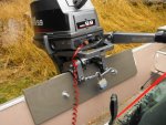
I think it was in another thread that we discussed the engine vertical position and the use of a transom jack. In these pictures I show a "quick fix" to raise the engine about 3/4" inch. The engine may still be too low but I will give it a try. The second picture shows I have added a 1/2" (exterior) plywood piece 2' by about 8" to help hold the spacer put on the top of the transom, visible in picture 1. The bolts through the transom are 5/16" stainless steel with a washer to spread the force on the backside of the transom (I many need larger washers such as can be seen on the inside, up against the plywood).
The other concern I have is the transom itself. The third and forth pictures are typical I think. To my eye it looks like I can gain access to the area between the inside and backside of the aluminum by removing the end caps, picture 3 shows the LH side, same on the RH side, and then remove the aluminum cap, about 1.5" wide, focused on in picture 4.
My plan is to replace the plywood inside this area as it seems to be gone or soft at the top. The boat is rated at 35 hp or less, I use and will use only the 9.9 hp shown.. and I don't use a transom saver when transporting the boat...never have with this size engine. The soft transom is as purchased used, not something I caused.
Welcome any reactions, especially to the plywood addition to act as a 3/4" transom jack extension. Does it look strong enough? I have run the engine at least 4 hours on this boat with the engine clamped to the transom with just a spacer between the two attachment screws and the inside of the transom, already described as soft.
I make slow progress, some has to be undone...
Here's an update/question to this thread and perhaps another one I started in the previous month which discussed transom jack (engine physical positioning) and a hydrofoil addition to the anti-cavitation plan on the engine to make it move more onto a plan when at full power. Boat is a 14' Discovery (Grumman like) and I think it wallows along when at full power.
I think it was in another thread that we discussed the engine vertical position and the use of a transom jack. In these pictures I show a "quick fix" to raise the engine about 3/4" inch. The engine may still be too low but I will give it a try. The second picture shows I have added a 1/2" (exterior) plywood piece 2' by about 8" to help hold the spacer put on the top of the transom, visible in picture 1. The bolts through the transom are 5/16" stainless steel with a washer to spread the force on the backside of the transom (I many need larger washers such as can be seen on the inside, up against the plywood).
The other concern I have is the transom itself. The third and forth pictures are typical I think. To my eye it looks like I can gain access to the area between the inside and backside of the aluminum by removing the end caps, picture 3 shows the LH side, same on the RH side, and then remove the aluminum cap, about 1.5" wide, focused on in picture 4.
My plan is to replace the plywood inside this area as it seems to be gone or soft at the top. The boat is rated at 35 hp or less, I use and will use only the 9.9 hp shown.. and I don't use a transom saver when transporting the boat...never have with this size engine. The soft transom is as purchased used, not something I caused.
Welcome any reactions, especially to the plywood addition to act as a 3/4" transom jack extension. Does it look strong enough? I have run the engine at least 4 hours on this boat with the engine clamped to the transom with just a spacer between the two attachment screws and the inside of the transom, already described as soft.