Wiring for digital iginition

Arrowglassrestorer

Seaman Apprentice
Joined
Feb 11, 2017
Messages
31
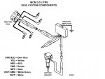
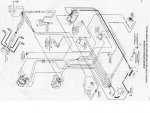
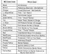
Restoring a 88 boat with alpha 1 3.0 which has digital ign. Problem is someone cut all the copper wire out of boat but left about 2 inches of wire at each location. I would like to replace the wiring by splicing in new wiring. I need to know where the different colors go to on the iginition system
This includes the rectangular box on manifold, the distributor and the coil pack. Everythingelse I can get from the shop manual
 

alldodge

Moderator
Staff member
Joined
Mar 8, 2009
Messages
42,643
Howdy
Merc still makes the harness for the non-digital 3.0L. Rewiring the motor to original to digital (DDIS) can work so long as the components are still usable. Note that these years used the BIA wiring colors, later the colors were changed. Hope this helps
Slide1.JPG
Slide3.JPG
Slide2.JPG
 
Last edited:

Scott Danforth

Grumpy Vintage Moderator still playing with boats
Staff member
Joined
Jul 23, 2011
Messages
50,355
Color codes are SAE standard.

Make sure to use tinned marine wire. EBAY has a complete 16 spool bundle of appropriate colors in 16 gauge marine wire cheap
 

Arrowglassrestorer

Seaman Apprentice
Joined
Feb 11, 2017
Messages
31
do you know if any of the wires in the ign system were resistor wire? Also what is the purpose of tinned wire? Corrosion resistant??
 

alldodge

Moderator
Staff member
Joined
Mar 8, 2009
Messages
42,643
do you know if any of the wires in the ign system were resistor wire? Also what is the purpose of tinned wire? Corrosion resistant??

A digital ignition does not use a resistor wire, these were for points ignition only

Tinned wire is better a reducing corrosion and is easier to solder. Been a lot of boats out there without tinned wire. If your not in salt water and you seal your connections IMO your OK. Other opinions will vary
 

Arrowglassrestorer

Seaman Apprentice
Joined
Feb 11, 2017
Messages
31
Okay the drawings were great and I have all the routing complete with exception of the gray wire coming out of the amplifier. The drawing shows that it goes through the plug as #2 wire. But where does the gray wire go after it leaves the plug.
 

Arrowglassrestorer

Seaman Apprentice
Joined
Feb 11, 2017
Messages
31
BTW I have this motor out of the boat and on a engine startup stand I intend to start it on the stand and tune it before I put it in the boat. So I need to know what to do with the gray wire to start the motor
 

Arrowglassrestorer

Seaman Apprentice
Joined
Feb 11, 2017
Messages
31
Also could you tell me where this system is getting the + current from. I see the ground but can't under stand where the current is coming in to the system from, according to the drawings
 

alldodge

Moderator
Staff member
Joined
Mar 8, 2009
Messages
42,643
Also could you tell me where this system is getting the + current from. I see the ground but can't under stand where the current is coming in to the system from, according to the drawings

System gets power from the purple wire coming from pin 5
 

Arrowglassrestorer

Seaman Apprentice
Joined
Feb 11, 2017
Messages
31
Wow why didn't I see that. Can you tell me where the # 5 goes to after it leaves the connector, on the boat side. Is it the iginition switch?
 
Top