I have been search online for this project for a while now. a lot of people take about it and only one I can find did it. but it doesn't have a lot of info on what components are needed. so I decided to do it my self and do it as cheap as possible. Here are the pictures.
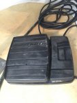
Original control
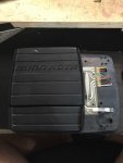
Open it up and cut the wire. The Yellow, Red Green wire is for rotation control,
Orange and Brown is for speed control
White is for On/Off control.
Black is ground, needed for all control to complete the circuit.
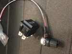
1 pc 10K OHM Linear Taper Rotary Potentiometer for $0.99
1 pc DPDT Momentary Rocker Switch
Cut 3/4" PVC pipe and flatten the top for controls attachment.
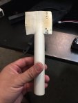
Cut holes. it is very easy to cut if you heat up the PVC, Heat also needed to flatten the top.
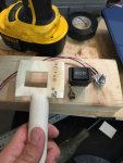
Controls installed
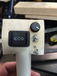
Roughly attached the wire for test. Will make it "nice" after testing. if you need the layout of the wire, I will post it later.
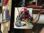
Completed.
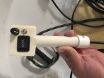
Here is a video to show the test result.
Original control

Open it up and cut the wire. The Yellow, Red Green wire is for rotation control,
Orange and Brown is for speed control
White is for On/Off control.
Black is ground, needed for all control to complete the circuit.

1 pc 10K OHM Linear Taper Rotary Potentiometer for $0.99
1 pc DPDT Momentary Rocker Switch

Cut 3/4" PVC pipe and flatten the top for controls attachment.

Cut holes. it is very easy to cut if you heat up the PVC, Heat also needed to flatten the top.

Controls installed

Roughly attached the wire for test. Will make it "nice" after testing. if you need the layout of the wire, I will post it later.

Completed.

Here is a video to show the test result.


