Nola Mike's 3.7/470 --> 4.3L swap thread

nola mike

Vice Admiral
Joined
Apr 22, 2009
Messages
5,526
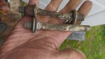
Ok, finally made it back. Compression was initially a little low. After some cranking, I ended up with 150-160 psi in all six.
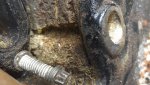
And then off with its head(s)!
Some carbon in there, but the cylinders looked good. Walls very smooth. Double checked the '89, it does have a roller cam btw. The '01 has a roller cam, and the rocker arms have a roller in the fulcrum as well, and appear to be the non-adjustable type. New engine was a manual, so I have a flywheel. The cover from the old one looks like it fits. Got the glass arriving tuesday. I'll clean and sand the bilge in the meantime. Aside from the HG and core plugs, what do I want to replace while I have the engine out? Gaskets? oil pump? Mounts?

IMG_20200424_144641.jpg

IMG_20200424_143028.jpg

IMG_20200424_142602.jpg
IMG_20200424_142613.jpg
IMG_20200424_142607.jpg

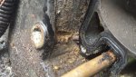
This one I'm just proud of my organization
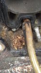
IMG_20200424_143410.jpg
 

Scott Danforth

Grumpy Vintage Moderator still playing with boats
Staff member
Joined
Jul 23, 2011
Messages
50,585
Auto mounts get tossed

Check timing chain play, best to check now and replace if needed.

Make sure you use a marine circulation pump
 

Lou C

Supreme Mariner
Joined
Nov 10, 2002
Messages
13,193
Pix look good from what we can see. How’s the cam & roller lifters look?
 

nola mike

Vice Admiral
Joined
Apr 22, 2009
Messages
5,526
Wow, F***n iboats just poofed away my whole long post after I clicked post TL;DR version:
1. I found transom rot, but I think it's salvageable.
2. I'm having a ***** of a time measuring the mount supports.

Lou C : Everything looked ok from what I could see. Didn't remove the shield covering the cam or the lifters. Guess I should probably do that.
Scott Danforth : I have all the original marine stuff that I'm going to swap over. May keep the squish mounts. If I have a problem, they don't look too hard to swap out.

The real excitement of the day. Going to try to keep it brief, since I don't feel like typing everything out again. My 2 lower studs on the transom plate were corroded, the port side stud was in 2 pieces. I dug rot out from around the studs. It extended to the interior/exposed portion of the keyhole, but surprisingly didn't go deeper. I drilled a few more holes around the transom plate, including down from interior of the cutout--all looked OK, and the one that should have been the worst (from the interior of the cutout) looked very good. So I think the rot is minor and localized, though concerning. It doesn't look like the keyhole interior surface was glassed, though tough to tell. Wondering if the rot started from inside the boat, directly exposed transom, but not sure. I'm planning on filling the voids around the bolts with 4200 unless someone has a better idea. The studs are just clamping the gimbal housing/transom plate together, so shouldn't be a structural concern. I retorqued the starboard stud, and there were no problems with tightening.

I tried using Rick Stephens template method to measure mount support height, but due to my transom not being 13' apparently (seems more like 13.5-14', still within spec) and because of imperfections in the transom surface (not smooth/resin) I couldn't get consistent measurements. I ended up screwing 2 boards together at 90', and resting one of them on the top surface of the transom mounts. More consistent, and consistent along the length of the stringers. Still getting 1/4" at least variation between measurements, which I'm not happy with. Where is the spec for the drop between the transom mount and the side mount? Rick says 4", but I'd like to verify. I also think Lowes gave me the wrong plywood, as it's measuring 3/8" (using steel rule, I don't have a mic with me here apparently) instead of 15/32. Wouldn't be a big deal, except that the only 3/8" is interior grade according to the web site. Grrr. 40 minutes each way to Lowes...
 

Attachments

  • photo329153.jpg
    photo329153.jpg
    419.8 KB · Views: 4
  • photo329154.jpg
    photo329154.jpg
    679.8 KB · Views: 5
  • photo329155.jpg
    photo329155.jpg
    1.3 MB · Views: 5
  • photo329156.jpg
    photo329156.jpg
    1.8 MB · Views: 5
  • photo329157.jpg
    photo329157.jpg
    2.1 MB · Views: 5

Scott Danforth

Grumpy Vintage Moderator still playing with boats
Staff member
Joined
Jul 23, 2011
Messages
50,585
grind out the rot, mush in some PB......re-drill
 

achris

More fish than mountain goat
Joined
May 19, 2004
Messages
27,468
Here's a pdf of the 4.3L installation drawing. Bearing in mind, this drawing is with standard engine mounts, and 15° dry joint elbows. If you use fluid mounts, recalculate the mount height.

4.3L MPI Alpha_1996-2004.pdf

Chris.......
 
Last edited:

Scott Danforth

Grumpy Vintage Moderator still playing with boats
Staff member
Joined
Jul 23, 2011
Messages
50,585
I would not use the squishy mounts, even with a non-balance shaft motor. its like trying to tow a trailer with a 50 foot bungee cord between the truck and the trailer....while it smooths out things a bit, performance really suffers.
 

Rick Stephens

Admiral
Joined
Aug 13, 2013
Messages
6,118
I think you missed the point entirely about how the motor sits 13º to the transom. Doesn't matter what angle the transom itself is. The motor is ALWAYS 13º to the transom. Always. If your transom is 17º like mine, then the motor is up at the front by 4º.

Alignment is dependent on this. When you look at your transom plate you will see that the driveline area is angled down. That angle is exactly 13º. Look at the gimbal housing, the gimbal bearing is also set square at 13º down. Centerline of the crankshaft will be 13º to the transom. There is a fairly wide range of transom angles approved for use by Merc. If your transom angle to the stringers was 10º (more straight up than yours or mine) then the motor will end up when in alignment, at 3º downwards.
 
Last edited:

nola mike

Vice Admiral
Joined
Apr 22, 2009
Messages
5,526
Rick Stephens , yes, I did miss that entirely. I thought the transom angle was relative to the stringers. I haven't glassed yet, but have the mount supports cut. I'll remeasure, though the part about the rough transom still in effect. This will add an inch or 2 to my mount pad height.

achris, that's the diagram I've been using, but I'm still not seeing that dimension. Closest is 3.5" crank center to mount base.

Ok, I'll use standard mounts. What's the difference in height?

Given all the uncertainty with my measurements, seems like a good idea to hold off the final glass work until I can dry fit the motor. I'll PB everything in place, cut the mat so I can do it quickly when the time comes...
Thanks for the continued help guys.
 

achris

More fish than mountain goat
Joined
May 19, 2004
Messages
27,468
...achris, that's the diagram I've been using, but I'm still not seeing that dimension. Closest is 3.5" crank center to mount base.....

Not sure which measurement you're looking for... Is this the question?

..... Where is the spec for the drop between the transom mount and the side mount? ...

If so, take a straight edge and run it across the flywheel housing rubber bushing bases (while on the engine). Measure the distance from your straight edge to the centre of the engine coupler. Take that measurement from 3.5" and you have your answer.... (I'll only be a few millimetres)

Chris.......
 

nola mike

Vice Admiral
Joined
Apr 22, 2009
Messages
5,526
Not sure which measurement you're looking for... Is this the question?


If so, take a straight edge and run it across the flywheel housing rubber bushing bases (while on the engine). Measure the distance from your straight edge to the centre of the engine coupler. Take that measurement from 3.5" and you have your answer.... (I'll only be a few millimetres)

Chris.......

Yes, that's the question. I'm surprised there isn't an actual dimension spec'd somewhere though. With all the measurements I'm doing, I'm compounding my errors/imprecision. Like I said, a dry fit before final glassing seems like a good idea. I built and measured the mount supports to 4" below as Rick suggested, using the 13' template. Pouring out today so I'm going to start a parts list, I'm going to PB them in tomorrow hopefully.
 

Rick Stephens

Admiral
Joined
Aug 13, 2013
Messages
6,118
Like you, when I built my mounts my block was in the machine shop. Everyone said drop the motor in, take it out, drop it in, take it out. Etc. The drawings do not really say 4 inches. They do show center of crank though, and they do show its relationship to top of transom plate motor mount. We can pretty well extrapolate about a quarter inch above crank center for the actual mount location without the leather pads. Could have gone 3.75 inches, but as you have been recommended, better to be a teensy bit low with your glassed in mount (and extend your mount adjustment or shim them) than a teensy bit high and have no adjustment. So I went 4 and it was on the money.

Click image for larger version  Name:	important marks.png Views:	1 Size:	271.5 KB ID:	10858355Click image for larger version  Name:	important close.png Views:	1 Size:	46.4 KB ID:	10858356
 

Rick Stephens

Admiral
Joined
Aug 13, 2013
Messages
6,118
One other thing, it is my understanding that the overall height of fluid mounts is identical to hard mounts. Don't have personal knowledge of that as I have only owned fluid mounts.
 

nola mike

Vice Admiral
Joined
Apr 22, 2009
Messages
5,526
Ok, thanks Rick. Didn't know where that 4" came from...Trust but verify, right? Right now I'm sitting about 3/8" below that 4" number, maybe a little less. Once I PB the supports in and glass, I'll probably be 1/8-1/4" off I'm guessing. 34 year old bilge=super nasty BTW. Surprised my pump worked at all given that the strainer was completely caked with crud/grease. Gonna have to add that as a maintenance item.
 

nola mike

Vice Admiral
Joined
Apr 22, 2009
Messages
5,526
And moving on to parts needed. Spent a long time today trying to track down part numbers and what I need. Please let me know if I'm off, or if anything else should be replaced:

1. Gasket set. I'm looking at fel-pro 17211, but it looks like that's for non-vortec heads. This is HG, intake, exhaust, valve cover. I'll call them tomorrow and see if they have a different kit.
1a. Do I need new head bolts or are they reuseable?
2. More gaskets: Carb, oil pan
3. Fuel pump. I'll need to get an electric pump. I've seen Carter P4389 mentioned, and A-68301 for the switch. Sound right? Also going to need a relay and fuse for the wiring, and 1/4" NPT tee.
4. Brass core plugs. 1 5/8", I found sets of them for V8s.
5. Intake. Cast iron GM part ~$250
6. Edelbrock 1409 carb, ~200 for used rebuilt
Still undecided about the mounts.

Stuff that's broken/needs replaced:
1. Thermostat and gaskets
2. Lower shift cable, boot, etc
3. Gimbal bearing/install tool/oil seal. I'm not sure what the tolerance ring is, it's NLA. Is that included with the bearing, is it needed? Looking at sealed unit
4. U-Joints. I used a Moog 315g last time, would prefer a sealed unit
5. Transom bolt kit. You'd think these things are made of gold instead of aluminum

Anything else at all that should be done with everything apart? Gonna order tomorrow, it looks like I should have done it earlier, I'm going to be waiting on some of this stuff.
 

achris

More fish than mountain goat
Joined
May 19, 2004
Messages
27,468
...3. Gimbal bearing/install tool/oil seal. I'm not sure what the tolerance ring is, it's NLA. Is that included with the bearing, is it needed? Looking at sealed unit

Tolerance ring is that crinkly bit of steel in the outer circumference of the bearing carrier. Comes with the bearing when you buy it. Sealed unit, :thumb: I think only Merc currently have the sealed units, but they're not that much more than a nasty greaseable aftermarket one anyway...

4. U-Joints. I used a Moog 315g last time, would prefer a sealed unit

Again, only Merc do the sealed ones, but good choice. ;)

Chris......
 

Rick Stephens

Admiral
Joined
Aug 13, 2013
Messages
6,118
I had to purchase individual top and bottom end Felpro gasket sets for my motor. I had a non-balance shaft block with Vortec top end.

The OEM fuel pump is an Airtec model E1103. Nice part with using it is you can get the mercruiser mounting bracket, fuel line fittings and stainless fuel line up to the carburetor.

I wired the pump in with a relay to power it. And a 10 amp fuse on the power circuit to the relay.

fuel system.jpg
 

nola mike

Vice Admiral
Joined
Apr 22, 2009
Messages
5,526
OK, so I called Fel-pro, and they said they don't make a marine gasket set for the vortec heads (or head gaskets, intake manifold). I was kind of under the impression that most/all head gaskets are composite these days anyway, and that that was the issue with it being marine.

Can I just use a standard Fel-pro top end set?
This Mahle set looked good, (HS744F) and includes water pump and distributor gaskets (forgot about those!)
Are the auto and marine exhaust gaskets different? I could see those having a different configuration for the water flow...
 
Top