1987 Sea Ray Sorrento Bow Rider Rebuild Project...

vandentr

Petty Officer 3rd Class
Joined
Jul 26, 2010
Messages
88
So I bought her 11 years ago, and because it was obvious that she had been somewhat neglected by her previous owners I immediately went through an overhaul process on the outdrive and engine components. I also wound up painting over the old red gelcoat due to significant wear.

Two years after buying her my 7 year old daughter became ill with a rare blood disease and we wound up in a 5 year battle for her life, which she ultimately won thanks to a successful bone marrow transplant 3 years ago!

As you can imagine, the boat was barely used during those 5 years and mostly remained in dry storage after being properly winterized.

Around this past 4th of July we decided it was time to get back into the swing of boating and get her out on the lake!

Forty five minutes after launching her, we were putting her back on the trailer because of the amount of water she was taking on, whether running or not. :facepalm:

Thus begins the saga of my restoration process...

Note: Pics are from the "early years", when things were great!
 

Attachments

  • photo319478.jpg
    photo319478.jpg
    71.7 KB · Views: 18
  • photo319479.jpg
    photo319479.jpg
    61.8 KB · Views: 20

vandentr

Petty Officer 3rd Class
Joined
Jul 26, 2010
Messages
88
Thanks Capri!

There is one primary reason I decided to take this on as a project, and that's because I work for a power sport and yachting company. So I not only have access to the supplies and tools at a reduced rate, but I have free access to decades worth of expertise to help insure a successful outcome. It would be a crime NOT to do it!

The first step was to investigate the bilge, transom, and gimble plate areas.

After pulling the engine I discovered that I could push a screwdriver from the gimble ring hole into the transom wood and all the way down to the hull.

This really didn't come as a shock to me and actually confirmed my suspicions because I couldn't see or hear the water coming in, and the bellows and other drive connections were all intact and dry. Also, the floor had been redone by a previous owner and I could see a fair amount of delamination along the bilge stringers.

So next up is removing all of the crap off transom and see how bad things really are...
 

Attachments

  • photo319482.jpg
    photo319482.jpg
    336.6 KB · Views: 19
  • photo319483.jpg
    photo319483.jpg
    234.4 KB · Views: 18
  • photo319484.jpg
    photo319484.jpg
    247.3 KB · Views: 17

vandentr

Petty Officer 3rd Class
Joined
Jul 26, 2010
Messages
88
After cutting a million brittle zip ties and disconnecting and removing all of the remaining hardware, I de-greased and washed out the bilge with my pressure washer. I then pried out the back section of the original floor from where it was mated to the "newer" floor all the way back to the transom and whacked about 6 inches of the stringers out with a sawzall so I had access to the transom fiberglass skin.

I used a 4.5" angle grinder with a metal cutoff blade to deskin the transom fiberglass and discovered that the wood behind it was a rotten disaster. This transom consisted of two pieces of 3/4" plywood that were glued together in the center, but were simply stapled together on the "wings".

The first board came of fairly easily, in about 4 chunks, which was because water had wicked between the two boards ALL the way up to the top. The second board was fairly well adhered to the transom fiberglass and took the bulk of my time to chisel out.

One good thing about the older Sea Ray's is that they're built like tanks and their hulls and transoms are extremely thick and rugged, so I had no issues prying against it!
 

Attachments

  • photo319486.jpg
    photo319486.jpg
    542.9 KB · Views: 25
  • photo319487.jpg
    photo319487.jpg
    426.9 KB · Views: 23
Last edited:

Selleck95

Cadet
Joined
May 14, 2018
Messages
15
I am currently in the middle of rebuilding basically the same boat. It is a 1989 though. I will follow this thread for sure. Great looking boat glad to see you are keeping it on the water.
 

vandentr

Petty Officer 3rd Class
Joined
Jul 26, 2010
Messages
88
Based on what I could see of the exposed stringers and flooring in and around the stern and the degree of rot in them along with a couple of soft spots toward the bow, I decided the floor had to go.

The floor was an interesting animal.

When a previous owner had it redone they yanked out the two back-to-back lounge seats and had 4 (cheap) captains chairs installed. The way the "installer" achieved this feat of engineering wonder was to attach pressure-treated 2x8 planks to the bottom of the new floor running fore and aft, one on the port side, and the other on the starboard side, and then bolted the chair pedestals through both the plank and the floor. To get these planks to lay flush with the top of the stringers they carved enough of the foam out between the stringers to allow them to be inset.

Also, it was obvious that the installer knew that the stringers were bad because they eliminated the original ski locker and put in a reinforced box of pressure treated plywood to support the surrounding stringers and the new floor.

As an added bonus, it was super-nice of them to just use regular steel hardware, screws, and staples to fasten everything together so they would be rusted into oblivion for the next guy (me) to deal with.

Have I mentioned that I hate foam? Because I do.

:mad2:

Tip: If you need to rip through a deck quickly, the Graff Speedcutter die grinder blade (see pic) is the shizzle! It only took about 10 minutes to zip around the perimeter of my floor with that thing. Just make sure your carpet is pulled back, as there's not a tool on earth that plays nice with marine carpet!
 

Attachments

  • photo319488.jpg
    photo319488.jpg
    320.6 KB · Views: 31
  • photo319489.jpg
    photo319489.jpg
    216.6 KB · Views: 27
  • photo319490.jpg
    photo319490.jpg
    381.5 KB · Views: 30
  • photo319491.jpg
    photo319491.jpg
    63.8 KB · Views: 20

vandentr

Petty Officer 3rd Class
Joined
Jul 26, 2010
Messages
88
Since literally every single piece of wood I uncovered, whether flooring or stringer, was wet and rotten I knew (with a sense of dread) that I was going to have to proceed forward into the bow section and under the port and starboard consoles.

Holy balls, I'm glad that part is over!

Step one was to carefully "carve" out the textured fiberglass bow floor with a 3" pneumatic 90 degree cutoff wheel, which actually worked quite nicely. I intend to reuses this piece if possible, so I just took my time and had the trusty Shopvac running to suck out the debris right as I was cutting through the floor, using this setup the dust was almost non-existent.

Step two was to get very creative with a 12" sawzall demolition blade and carefully carve out the remaining flooring from under the consoles, the seat boxes, and behind the very front seat. After a while you get a feel for your depth and can easily tell when you've gone too deep and are bouncing off the hull.

Step three was to carve and pry out the remaining foam.

As I've said before, everything wood was wet and rotten, from bow to stern. Even the vertical console supports were rotten 2/3 of the way up from the floor! With regard to the foam, however, it was only moist where it was in contact with the hull or stringers. Outside of that it was completely dry, and no pooled water anywhere.

My guess is that this thing either sat out uncovered for an extended period of time or was somehow subjected to a swamping at some point.

This is as far as I've gotten, so in my next update I'll be cutting out the stringers and beginning to prep for grinding.

Pic Note: Check out the degree of rot on the visible parts of the stringers. :faint2:
 

Attachments

  • photo319492.jpg
    photo319492.jpg
    255.6 KB · Views: 28
  • photo319493.jpg
    photo319493.jpg
    172.6 KB · Views: 24
  • photo319494.jpg
    photo319494.jpg
    193.2 KB · Views: 25
  • photo319495.jpg
    photo319495.jpg
    145.9 KB · Views: 26
  • photo319496.jpg
    photo319496.jpg
    191.9 KB · Views: 22
  • photo319497.jpg
    photo319497.jpg
    464.7 KB · Views: 22
  • photo319498.jpg
    photo319498.jpg
    439.2 KB · Views: 23
  • photo319499.jpg
    photo319499.jpg
    230.4 KB · Views: 23

tpenfield

Moderator
Staff member
Joined
Jul 18, 2011
Messages
18,137
Nice work so far. :thumb: Make sure you take lots of measurements so you can refer to them on the rebuild.
 

vandentr

Petty Officer 3rd Class
Joined
Jul 26, 2010
Messages
88
Last night I spent a couple of more hours in demolition mode. My goal is to get this sucker ready for grinding by the weekend because I want to try to knock that out in one full day if possible.

I whipped out my 4.5" angle grinder and that Graff wood blade I referred to earlier (have I mentioned that awesomeness of that blade?) and started hacking away at the stringers.

When I finally called it quits, stood up, wiped all the crap off my goggles, and looked around, the only things left standing were the bilge bulkhead and engine mounts. I also trimmed the outer lip of the tabbed floor back to within 1 inch or less of the hull and removed the remaining foam from underneath it.

Of note is the false bottom along the keel. I'm not sure how common that "feature" is, but you can see the square "drain hole" in the back of the ski locker and then the 3/4" PVC that runs underneath the fuel tank and drains into the bilge as I've circled them in the related photos.

Should I cut that out and redo it as well, or just leave it? I can only imagine what it must look like under there!

Trimming the bow section under the seat boxes and consoles to prep for grinding will take a more delicate approach in order to avoid whacking through the hull, so I'm saving that task as well as one more pass at trimming the former stringer tabs as low as I dare for when I have my full wits about me and the best lighting conditions as possible.

Tips:

If you decide to take on a project like this I recommend three things for the demolition phase:

1) During the time you set aside to work on it, work your ass off and don't think about how much it sucks or how long it's going to take. The more you focus on your objective the quicker you will be on to the next phase.

2) Take time to clean out the boat at the end of each work session. Your sense of accomplishment will be much higher because you can see your progress, the boat will be ready for whatever is coming next, and it'll drastically reduce the amount of free-floating fiberglass in your working area.

3) It goes without saying, but it cannot be overstated, how important the right tools and protective clothing are for doing this work!
 

Attachments

  • photo319741.jpg
    photo319741.jpg
    275.2 KB · Views: 16
  • photo319742.jpg
    photo319742.jpg
    504.8 KB · Views: 15
  • photo319743.jpg
    photo319743.jpg
    224.4 KB · Views: 15
  • photo319744.jpg
    photo319744.jpg
    318.6 KB · Views: 18
  • photo319745.jpg
    photo319745.jpg
    193.5 KB · Views: 18
  • photo319746.jpg
    photo319746.jpg
    535.8 KB · Views: 19

vandentr

Petty Officer 3rd Class
Joined
Jul 26, 2010
Messages
88
I'm still working to get this thing prepped for grinding over the weekend, we'll see how it goes.

In the meantime, I managed to come up with the transom and partial stringer layouts direct from Sea Ray in the event that there's still another Sorrento floating around out there in need of some TLC.
 

Attachments

  • photo319864.jpg
    photo319864.jpg
    76.5 KB · Views: 27
  • photo319865.jpg
    photo319865.jpg
    177.7 KB · Views: 27
  • photo319866.jpg
    photo319866.jpg
    226 KB · Views: 24
  • photo319867.jpg
    photo319867.jpg
    305.8 KB · Views: 27

kcassells

Fleet Admiral
Joined
Oct 16, 2012
Messages
8,738
Too tech for me.....where's my sawsall? Looks like a patent lawyer stuff. Is cool. :)
 

GCartwright

Petty Officer 2nd Class
Joined
Jul 1, 2012
Messages
149
Last night I spent a couple of more hours in demolition mode. My goal is to get this sucker ready for grinding by the weekend because I want to try to knock that out in one full day if possible.

Of note is the false bottom along the keel. I'm not sure how common that "feature" is, but you can see the square "drain hole" in the back of the ski locker and then the 3/4" PVC that runs underneath the fuel tank and drains into the bilge as I've circled them in the related photos.

Should I cut that out and redo it as well, or just leave it? I can only imagine what it must look like under there!


On my 91 Searay, the area under the tank floor was full of water and the pvc drain pipe was in pieces, I had a centre stringer there as well that was rotted out.

I recommend opening it up
 

Attachments

  • photo319894.jpg
    photo319894.jpg
    214.6 KB · Views: 22

vandentr

Petty Officer 3rd Class
Joined
Jul 26, 2010
Messages
88
Yep GC, that was the consensus from the guys at work too, so that's what I did.

My discovery was the same as yours, the original false-bottom wood support was basically a brown pasty goo and the center support it sat on oozed water when I squeezed it from the sides.

The sad thing about this boat is that the only pieces that were glassed and tabbed to the hull on both sides were that center stringer along the keel (shown in your pic), the stringers on each side of the bilge, and the 3 bulkheads.

The outer stringers were simply bedded in some bondo and held in with foam while the inner stringers around the fuel, and ski locker were only tabbed on the inside.

This thing was doomed to fail from the factory. :rant:

I'll post some pre-grinding pics later today...
 

vandentr

Petty Officer 3rd Class
Joined
Jul 26, 2010
Messages
88
Well, I didn't quite get to the grinding, but I'm pretty close.

The trailer I've got is an easy loader with wheels, so I had to get the majority of the weight of the boat off of those roller wheels and onto some heavy-duty jack stands I positioned in the rear corners. As part of that process I also leveled her from port to starboard and then raised the trailer back up to the point of being supportive, but not load bearing, in order to maintain the natural shape of the hull without any dimpling or wavy distortions.

Inside the boat, I secured the forward motor mounts with some 1x4's to capture the distance between them and to the transom (knowing I'll eventually have to subtract the measurement to the transom after the new one is in place and skinned over) and then removed them with the oscillating saw.

The outer transom glass is definitely in need of some TLC. There's some previous repair areas that need filling, and then some sort of separation around the "bowling pin" cutout that I've depicted in the photo's.

As I eluded to in post #15, the sub-floor construction on this boat was doomed from the factory.

From a rebuild standpoint it's great great that they essentially glued this thing together with bondo because it means that much less grinding I'll have to do, but sacrificing quality to cut costs seems counter-intuitive to me.

Nearly all of the tabbing that was used, which was minimal at best, has essentially peeled off without much effort. For example I ripped out the port floor lip in nearly one piece after getting it started with the chisel. Only the center keel support tabbing on the starboard side had a bond strong enough that I couldn't pry it off.

I'm working at making sure I get as much of the bondo and weak tabbing out of this beast as possible because I want the grinding to be as efficient and trouble-free as possible!
 

Attachments

  • photo320136.jpg
    photo320136.jpg
    103 KB · Views: 17
  • photo320137.jpg
    photo320137.jpg
    412.6 KB · Views: 17
  • photo320138.jpg
    photo320138.jpg
    136.9 KB · Views: 17
  • photo320139.jpg
    photo320139.jpg
    247.3 KB · Views: 15
  • photo320140.jpg
    photo320140.jpg
    531.7 KB · Views: 15
  • photo320141.jpg
    photo320141.jpg
    465.2 KB · Views: 14
  • photo320142.jpg
    photo320142.jpg
    271.1 KB · Views: 13
  • photo320143.jpg
    photo320143.jpg
    271.2 KB · Views: 16
  • photo320144.jpg
    photo320144.jpg
    342.6 KB · Views: 16
  • photo320145.jpg
    photo320145.jpg
    406.8 KB · Views: 17

AShipShow

Lieutenant Commander
Joined
Jul 8, 2016
Messages
1,803
My transom was not far off of yours.. I ended up using some PB and filled all the low spots and used a straight edge to help fair the resin to make the surface as flat an uniform as possible. Then I put a new layer of 1708 on the transom before glueing in the new wood. It doesn't need to be absolutely perfect because the PB will fill irregularities when you install the new wood.
 

vandentr

Petty Officer 3rd Class
Joined
Jul 26, 2010
Messages
88
OK, so even though it’s been a while since my last update, I’ve been busy working on several different aspects of the rebuild process in the background as time has allowed.

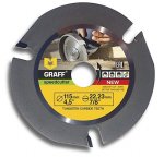
With regard to the grinding, my plan was to start with the transom and then work my way to the bow. I figured that since this was my first time ever using an angle grinder it’d be good to work on something large and relatively flat. I alternated between a new 4.5” grinder I bought (which is much less fatiguing on the hands and arms) and a borrowed a 6” behemoth grinder using 24 and 40 grit ceramic grinding disks.

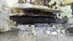
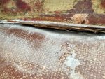
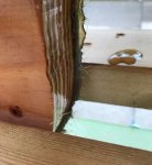
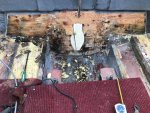
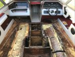
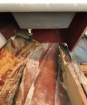
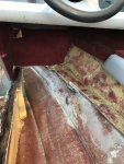
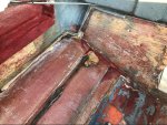
The transom grinding started good and was going along fine until I got to the port side, where I ran into my first snag.

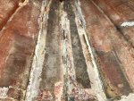
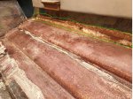
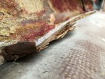
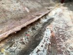
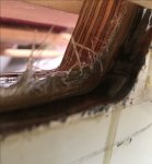
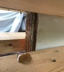
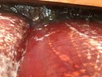
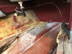
Underneath the wood that I was grinding off I discovered that the port side of the transom had developed a huge fiberglass void from a poorly sealed hole (or holes) that extended from the upper and outer edge of the transom all the way across and downward to the gimbal opening, which had then compromised the middle two gimbal mounting bolt holes. As I ground out the delaminated fiberglass, the grinder was actually flinging water that was STILL resting in the bottom of the void between the inner and outer fiberglass!

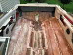
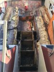
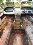
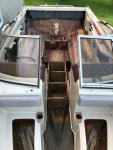
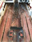
After getting that all removed, I spent the next couple of weekends grinding the hull in preparation for the new stringer, bulkhead, and floor tabbing from stern to bow as I had planned. Those were some long days and my back is happy to say that, outside of a few left over touch-up spots, it’ll NEVER have to do that job again, hallelujah! I’ll provide some overall before and after pictures for that aspect of the demolition and hull prep work in a future update.

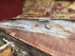
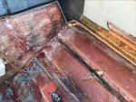
In the meantime, I was researching the best way to restore the transom to a point where it was ready to accept a new transom core.

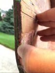
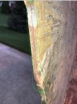
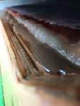
The formula I decided to use for the repair was thickened resin (using cabosil) with a fair amount of .25” chopped fiberglass strands added for strength and flexibility. It took 4 or 5 iterations of slathering a 10-16oz mixture into the void and various low spots with a paint stick, fairing out the edges, covering it all with waxed paper and smoothing it out with a flat edge, then coming back the next day and sanding out any pockets and checking for flatness until it was FINALLY built back up to where it should be.

While all of that was going on, I was getting all sorts of help and advice on building and installing the new transom board.

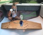
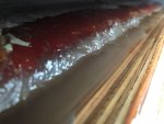
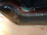
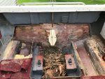
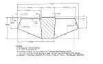
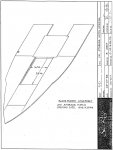
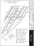
The pattern of the new transom board was made from a template that was traced and cut out of foam board, then digitized into a CNC file, and finally cut out of 7-ply marine grade plywood. The specs called for a 1.5” thick board so we cut two .75” copies out and then clamped them together using TiteBond III waterproof wood glue as the bonding agent. The next day, to make the future fiberglass laminating easier, we routered the entire outer parameter flat and routed a rounded edge on the top and side front edges. When all was said and done it was difficult to see the bonding layer between the two boards, nice!

For the gimbal (or bowling pin) cutout, I test-fit the board against the transom and blocked it into place with wood shims, then had my wife trace the cutout and the bolt holes from the outside while I leaned on it from the inside. I then took the board back out and drilled out just two of the six bolt holes (diagonally opposed) to a smaller dimension, then bolted the transom back into the boat and retraced the opening and drilled out the remaining bolt holes. Once again, I took the sucker back out of the boat put it on a couple of saw horses and used a jig saw to cut out the gimbal opening to within .25”, then put it back in the boat, bolted it up, and used a 2” router bit to remove the remaining transom wood following original fiberglass cutout as the trace. It was definitely time consuming, but I don’t like doing things twice and it came out as close to perfect as I could get.

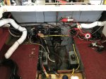
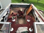
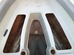
Finally, after all of that and resin-coating both sides of the board earlier this week, Lilly and I were able to put it in last night!

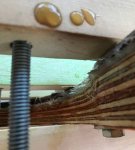
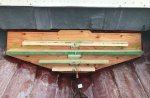
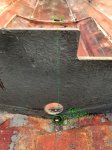
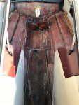
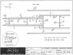
I followed the advice I was given and wetted out the back of the new board, then wetted out two layers of 1.5oz CSM, then wetted out the transom, and clamped that ***** into place with my “custom” 2x4 clamping system and the gimbal bolts (which I slathered with grease beforehand).

Needless to say, resin squished out of everywhere!
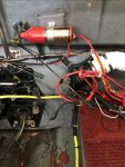
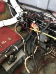
Note: You can see the pooled resin around the parameter denoted on the clamp picture (red) and the clamping “feet” attached to the long 2x4’s to apply pressure to the outer edge of the transom “wings” (green).

I put the cover on and put a small space heater in the boat overnight and this morning the resin was like concrete!

Whew, consider yourselves caught up! The next steps are puttying around the parameter of the board, tabbing it in, and overlaying it with a couple layers of 1708, which I hope to do over the weekend.
 

Attachments

  • photo320927.jpg
    photo320927.jpg
    173 KB · Views: 24
  • photo320928.jpg
    photo320928.jpg
    77.1 KB · Views: 20
  • photo320929.jpg
    photo320929.jpg
    100.3 KB · Views: 17
  • photo320930.jpg
    photo320930.jpg
    96.9 KB · Views: 16
  • photo320931.jpg
    photo320931.jpg
    120.8 KB · Views: 16
  • photo320932.jpg
    photo320932.jpg
    96.6 KB · Views: 17
  • photo320933.jpg
    photo320933.jpg
    95.3 KB · Views: 15
  • photo320934.jpg
    photo320934.jpg
    307.4 KB · Views: 20
  • photo320935.jpg
    photo320935.jpg
    262.8 KB · Views: 20
  • photo320936.jpg
    photo320936.jpg
    174.2 KB · Views: 17
  • photo320937.jpg
    photo320937.jpg
    139.5 KB · Views: 15
  • photo320938.jpg
    photo320938.jpg
    170.8 KB · Views: 21
Top