115 6c TOP piston cylinder issue

jimmbo

Supreme Mariner
Joined
May 24, 2004
Messages
14,435
600-650rpm, in Forward was the Idle Speed Spec for those engines. I used to adjust them for 575-625, just to lower the Shock imposed on the Driveline when put into Gear.
Regarding your Piston Rings. You are checking their End Gaps in their assigned Cylinder at several spots, and adjusting if necessary before installing them on the Pistons?
 

ianmoore

Petty Officer 1st Class
Joined
Jun 5, 2014
Messages
236
600-650rpm, in Forward was the Idle Speed Spec for those engines. I used to adjust them for 575-625, just to lower the Shock imposed on the Driveline when put into Gear.
Regarding your Piston Rings. You are checking their End Gaps in their assigned Cylinder at several spots, and adjusting if necessary before installing them on the Pistons?
Ive never installed a piston in a cylinder, so lets start there!

Do you have any thoughts on my question? I had compiled some notes on assembly. One person had mentioned checking end pin by turning the piston in the cylinder after it was installed.

My question/concern was that i thought the rings went in well and the pistons all seemed to behave similarly. I was under the impression that a ring not properly seated was pretty easy to feel. I think that the ring might have broken in the cylinder when i turned it to try to see the ring stops. Those ring ends would never come close to the ports on the side of the pistons, and possibly the gap got caught there?

I don't have ring compressors, so I was using fingers/plastic tools to install them.

I did not check the rings separately. I was following my merc manual on piston install. The only thing it said regarding rings was to test by pressing with a screwdriver after install to see if it had some spring

i had cylinders and pistons prepped.
I did my best to center the two rings around the ring gap
I then slowly compressed the rings until piston sat in cyliner.

i had one or 2 times where it didn't go in quite right and i gently pulled it out to redo.
 

jimmbo

Supreme Mariner
Joined
May 24, 2004
Messages
14,435
Even though, in theory the Rings should fit, the Piston Rings Gaps should be checked and Adjusted to each and every Cylinder Bore. A lot of Machine Shops will require the Intended Pistons be supplied to them with the Block, so they can be measured(even brand new Parts can vary slightly in size), and the Cylinder is bored specific to that Piston. But the Rings are usually not fitted by the Machine Shop. Using the Piston to push a Ring down the Cylinder, insures the Ring is Perpendicular to the Cylinder Walls. The Gap in the Ring, is then Measured with Feeler Gauges, and the Number Recorded. There are several Specific Locations along the Cylinder Bore where the Ring needs to be placed and the Gap Checked.
If the Gap is too Big, the Leakage Loss will be higher than desired, if the Gap is too Small, the Ring will expand as the Motor Warms up closing the Gap, and Bad Things will then proceed to happen. A small Gap can be filed, and remeasured, until it meets the Proper Gap.
The Screwdriver Test is to Verify that the Ring isn't Broken.
The Pin is to, as you state, prevent the Rings from walking around the Piston, but they have been known to break too. Piston Rings, while Brittle, are pretty Tough, and can really chew up a Piston Crown and Cylinder Head bouncing around in the Combustion Chamber.
Rotating a Piston in a Cylinder, with the Rings installed is really not a good Idea
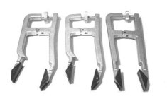
Installing the Pistons of on a lot of the Older Mercs, without the Special Ring Compressors, was a Challenge. 2 Sets of these were required on the Inline 6
zzez.jpg
It could be done without them, but it was not fun.
All the Connecting Rods with Pistons installed were attached to the Crankshaft and lowered together into the Block. On some Engines made after the 70s the Connecting Rods used End Cap Bolts that faced the Front of the Engine, on these, sometimes you could get away with putting the Pistons in first and then placing the Crank in. On the older Motors, the Con Rods had Bolts with Nuts that were located towards the Rear of the Motor.
If your has the End Cap Bolts, they are a One Time Use Only Bolt, and MUST be replaced.
 

ianmoore

Petty Officer 1st Class
Joined
Jun 5, 2014
Messages
236
Even though, in theory the Rings should fit, the Piston Rings Gaps should be checked and Adjusted to each and every Cylinder Bore. A lot of Machine Shops will require the Intended Pistons be supplied to them with the Block, so they can be measured(even brand new Parts can vary slightly in size), and the Cylinder is bored specific to that Piston. But the Rings are usually not fitted by the Machine Shop. Using the Piston to push a Ring down the Cylinder, insures the Ring is Perpendicular to the Cylinder Walls. The Gap in the Ring, is then Measured with Feeler Gauges, and the Number Recorded. There are several Specific Locations along the Cylinder Bore where the Ring needs to be placed and the Gap Checked.
If the Gap is too Big, the Leakage Loss will be higher than desired, if the Gap is too Small, the Ring will expand as the Motor Warms up closing the Gap, and Bad Things will then proceed to happen. A small Gap can be filed, and remeasured, until it meets the Proper Gap.
The Screwdriver Test is to Verify that the Ring isn't Broken.
The Pin is to, as you state, prevent the Rings from walking around the Piston, but they have been known to break too. Piston Rings, while Brittle, are pretty Tough, and can really chew up a Piston Crown and Cylinder Head bouncing around in the Combustion Chamber.
Rotating a Piston in a Cylinder, with the Rings installed is really not a good Idea
Installing the Pistons of on a lot of the Older Mercs, without the Special Ring Compressors, was a Challenge. 2 Sets of these were required on the Inline 6
View attachment 417649
It could be done without them, but it was not fun.
All the Connecting Rods with Pistons installed were attached to the Crankshaft and lowered together into the Block. On some Engines made after the 70s the Connecting Rods used End Cap Bolts that faced the Front of the Engine, on these, sometimes you could get away with putting the Pistons in first and then placing the Crank in. On the older Motors, the Con Rods had Bolts with Nuts that were located towards the Rear of the Motor.
If your has the End Cap Bolts, they are a One Time Use Only Bolt, and MUST be replaced.
Wow! Thanks for the details. This is all such an education.

I wish I had that communication and detail from the machine shop. Honestly, I thought I wasn’t going to be able to get anyone to do the work and was gonna be sitting on a broken block.

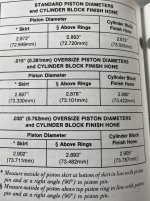
That said, I have very little detail on what was done. I am assuming the cylinders are slightly out of round, but was told that the existing pistons would work, so I ordered replacements.

I am going to go through the cylinders with rings to measure. I have the official merc repair manual, but did not see any info on this in the powerhead section. Perhaps it’s in a different place.

Yes, i wish I had the piston ring compressors, but I don’t, so will have to install crankshaft after pistons are in. Thankfully the rod bolts are the screw in type, so it is more doable
 

Chris1956

Supreme Mariner
Joined
Mar 25, 2004
Messages
28,920
Gee, I hope I am not redundant. Usually, you use the pistons to push the rings into the block, so they are perpendicular to the bore. Then use a feeler gauge to check end gap and file to proper clearance.

Screw-in or bolts with nuts are about the same difficulty when reassembling the rod-to-crank. The hard part is sticking the rod bearings onto the journals and cages, with grease. It is not really hard, but tedious. Hopefully you separated the bearings and cages by rod, so reassembly is easier.
 

ianmoore

Petty Officer 1st Class
Joined
Jun 5, 2014
Messages
236
Gee, I hope I am not redundant. Usually, you use the pistons to push the rings into the block, so they are perpendicular to the bore. Then use a feeler gauge to check end gap and file to proper clearance.

Screw-in or bolts with nuts are about the same difficulty when reassembling the rod-to-crank. The hard part is sticking the rod bearings onto the journals and cages, with grease. It is not really hard, but tedious. Hopefully you separated the bearings and cages by rod, so reassembly is easier.
No! I appreciate the time and detail. This is all new to me. It is strange that it doesn’t talk about ring gap in the manual, but I’m going back through and measuring that now. I had about .006 at 1” and bottom in c2(standard). That was the one I broke the ring on, but again, think it was from turning it in bore so ring end caught on port. C3(.0015) was about .008 at 1” and bottom
 

ianmoore

Petty Officer 1st Class
Joined
Jun 5, 2014
Messages
236
Gee, I hope I am not redundant. Usually, you use the pistons to push the rings into the block, so they are perpendicular to the bore. Then use a feeler gauge to check end gap and file to proper clearance.

Screw-in or bolts with nuts are about the same difficulty when reassembling the rod-to-crank. The hard part is sticking the rod bearings onto the journals and cages, with grease. It is not really hard, but tedious. Hopefully you separated the bearings and cages by rod, so reassembly is easier.
I did split rod bearings, cages, and caps, by piston. I am getting some real micrometers, and a decent dial bore guage. I'm going to go through the cylinders and get some numbers. This is too much work to just slap it together(Ive rebuilt everything but lower unit) and I want to make sure it is all good. The machinist was just too vague
 
Top