I/O (Sterndrive) Conversion to Outboards

tpenfield

Moderator
Staff member
Joined
Jul 18, 2011
Messages
18,477
Ted, since you would be having the fab work done externally if aluminum and you would have to build plugs/mold/parts if fiberglass, how is that easier?
Good question . . .

If I do fiberglass, I can potentially make the bracket a hull extension spanning across a greater width of the transom's irregular shape; basically going to/near the inside of the trim tabs.

If I do aluminum, it would be more feasible to make it as a bracket, just covering the width of the straight/flat portion of the transom.
 

Scott Danforth

Grumpy Vintage Moderator still playing with boats
Staff member
Joined
Jul 23, 2011
Messages
51,351
Ted, I was going.... you simply pay to have a fabricator make the aluminum bracket (no mater what shape) and you have to physically do the work yourself to do it out of fiberglass.
 

tpenfield

Moderator
Staff member
Joined
Jul 18, 2011
Messages
18,477
September Update . . .

Boating season (for us) has come to a close, and over the past few months I have been firming up plans for the outboard conversion. My 3D modeling software has come in handy in finalizing the design.

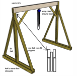
I plan on making a gantry for the heavy lifting . . . the rear seat assembly has to come off in order to pull the engines. . . probably weighs 400 lbs. Then I can use the gantry to pull the engines.
.
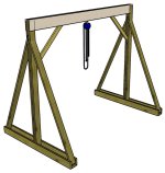
gantry-123.jpg
.
I am going with an outboard bracket that will also serve as a hull extension, what I am calling an 'extendo-bracket' :LOL: .

In designing the bracket, I wanted to take the shape of the boat's transom into consideration.
.
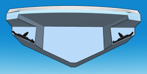
338-Transom-5.png
.
The 'flat' part of the transom is inset quite far and covers only about half of the boat's beam.
.
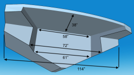
338-Stern-View-800-Dims.png
.
If I went with a traditional bracket, it would be only about 58" wide. Certainly wide enough for the twin engines, but probably falling short on the hull extension/planing surface criteria. So, I decided to go with the 72" width as a compromise, not messing with the trim tab areas.

Another consideration was fiberglass vs. aluminum. If I go with aluminum, I would probably want to have a space between the top of the bracket and the underside of the swim deck (corrosion prevention consideration). This would mean that the bracket would need to 'hang' off the transom. Considering the proposed length of the bracket ( 65") . . . that seems like a lot of cantilever.

If I go with fiberglass, (probably Coosa-cored fiberglass construction) I can more readily attach the bracket to the underside of the swim deck, making it be more like a hull extension. The contact areas of the extendo-bracket will be something like this . . . (shown in orange)
.
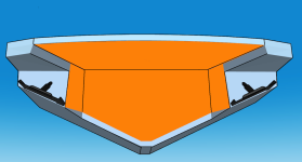
Hull-1-contact-area.png
.
The extendo-bracket will have the mating contact areas as illustrated below. . .
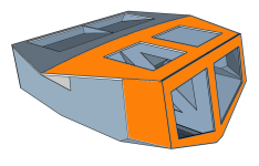
Ext-Brkt-1-B.png
.
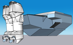
The installed extendo-bracket will look something like this . . .
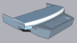
338-Stern-Top1.png
.
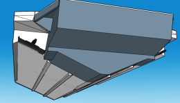
I am planning on a 2" step of the hull extension portion and its planing surface length will be about 40".
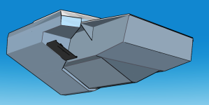
338-Stern-Bottom1.png
.
There will be adhesive and lots of fasteners holding the extendo-bracket to the boat.
.
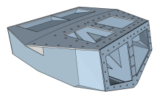
Ext-Brkt-hardware-holes.png
Probably about 80 fasteners (SS bolts) in total. My technical assessment is that 'it's not moving' . . .

Cruisers Yacht sent me pictures and drawings of the OB version of their boats a while back, so I could see how they add bracing to the transom area in support of the bracket. I plan on doing something similar with an added 'cross bar' at the top of the transom. (The bracing is shown in white, added to the top of the existing stringers).
.
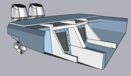
Swimdeck-Cavity.png
.
As for the engines, I am thinking 300 HP for the twins . . .
.
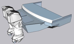
Swindeck-1.png
.
Speaking of engines: I've got some quote requests out and have a first set of #'s back . . . A bit more than I had estimated, but not terribly so. The quote I have is all the top-shelf stuff, more than what I was looking for, so there should be some wiggle room. Basically the controls and rigging are more than the cost of an engine :rolleyes: . . . .

Anyway, I'll post updates as things get rolling . . . the boat will be coming out of the water in the next week or so, then the conversion will be 'Job 1' for the next few months.
 
Last edited:

Scott Danforth

Grumpy Vintage Moderator still playing with boats
Staff member
Joined
Jul 23, 2011
Messages
51,351
Ted, the gantry is similar to what I used in my storage unit back in 2011. I did not use the kick braces on the sides, instead using plywood. the walls of the storage unit helped.

your legs of the A should be turned 90 degrees

your fully dressed motors are closer to 800#. the A-frame tweaks below will pick 1500# without a problem
1756994487776.png
 

tpenfield

Moderator
Staff member
Joined
Jul 18, 2011
Messages
18,477
One thing that I am still thinking over (or maybe over thinking :LOL: ) is the 2" step (up) of the extended planing surface. I see a lot of hull extensions that are done with the added planing surface flush with the existing hull, rather than a step. I'm thinking the step will allow some air underneath the added planing surface, much like a stepped hull design.

I'm still looking for some real-world examples.
 

tpenfield

Moderator
Staff member
Joined
Jul 18, 2011
Messages
18,477
As for stats & numbers . . .

If I build the extendo-bracket (EB) myself, it is looking like $5-6K including the gantry for materials and supplies. I am thinking to have one made is probably $12-15K.

I have estimated the weight of the bracket in foam/fiberglass at 475-500 lbs. If aluminum, I came up with about 630 lbs.

As for buoyancy, the EB will add about 1700 lbs of buoyancy to the stern, so I calculated roughly 2.5" of lift at the stern. With the I/O engines, I was always looking to move weight forward. Upon the conversion, I'll probably be looking to move things towards the stern a bit.

As for budget, I am looking at a total of $85-90K all-in. I am having shops quote a 'trade-in' of the I/O engines and controls as part of the deal.
 
Last edited:

tpenfield

Moderator
Staff member
Joined
Jul 18, 2011
Messages
18,477
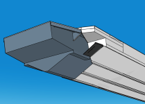
The more I read about the design of hull steps, the less inclined I am to having the 2" step. Here is a rendering of the E.B. without a step. There is a strake right at the chine of the extension (not previously detailed) that I could run to the end of the extension.
.
No-step-design-1.png
 

tpenfield

Moderator
Staff member
Joined
Jul 18, 2011
Messages
18,477
After some review of the boat hull (from pictures), I realized that I had the hull strakes slightly off. The upper strake does not line up exactly with the chine of the hull extension. Here are a couple of pictures with the strakes shown and adjusted accordingly.
.
Hull-Ext-Strakes-4.png
.
Hull-Ext-Strakes-3.png
.
I should be getting some more engine pricing over the next couple of weeks. . . . Later this month the 'fun' starts.
 
Last edited:
Top