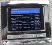
2016 Mercruiser 6.2 ECT - long beep every few minutes???

tpenfield

Moderator
Staff member
Joined
Jul 18, 2011
Messages
18,138
Usually a voltage divider type sender should be around 10k ohms. I've not measured one on a MerCruiser though. (Maybe something I should do)...
10K ohms would work . . . I can get a linear Potentiometer at that resistance range,
 

nola mike

Vice Admiral
Joined
Apr 22, 2009
Messages
5,411
Usually a voltage divider type sender should be around 10k ohms. I've not measured one on a MerCruiser though. (Maybe something I should do)...
10K ohms would work . . . I can get a linear Potentiometer at that resistance range,
Was going to suggest that... You also have another sender on the other side, no?
 

tpenfield

Moderator
Staff member
Joined
Jul 18, 2011
Messages
18,138
I'm going to upgrade my Diacom software today and see about getting the right cables. I won't be back at the boat until next week, so hopefully I'll have what I need to take the diagnostics to the next level.

These VesselView warnings are about as useful as a Check Engine Light :rolleyes:
 

tpenfield

Moderator
Staff member
Joined
Jul 18, 2011
Messages
18,138
Hope it does the trick

Me too !!! :LOL:

It should, since I'll know more of what is going on behind the curtain. . . so-to-speak. $330 for the cables is probably small $$$ in the long run, considering the amount of things that can go wrong with these engines. I'm waiting on a 'USB Configuration File' from Rinda, so I can update the cable (I did have the right cable though :D)
 

tpenfield

Moderator
Staff member
Joined
Jul 18, 2011
Messages
18,138
I also needed to upgrade the USB cable itself . . . which was not free :rolleyes:

The software upgrade itself was free, since I already had a prior version.
 

tpenfield

Moderator
Staff member
Joined
Jul 18, 2011
Messages
18,138
This Diacom stuff has gotten pretty expensive . . . but . . . it still pays for itself with the first diagnosis and repair vs. sending the boat to the local marine mechanic. :cool:
 

muc

"Retired" Association of Marine Technicians...
Joined
Jul 7, 2004
Messages
2,170
I recommend that you repair the trim sender. Especially with Axius a lot of these systems are inter connected and a fault in one system can have cascading effects in other systems. Like disconnecting the warning horn, the PCM know this and will do all sorts of things to try and protect the engine. If you need to do something with the warning horn, find it and wrap it up with electrical tape. But remember it’s there to try and save your life and money.

Yes you have a PCM 112.

The helm-1 low voltage fault is a critical return to port fault and I suggest you focus on that. This is a message that can have many different causes and is also one of the things that can cause your wheel stop fault. As near as I can tell. There are 3 possible sources for low voltage fault. Power to the TVM, power to the helm and keep alive power. It can be important that all of these have good connections and are connected to the right places. I have seen more than a few problems caused by the keep alive power and ground getting connected to the wrong battery when the boat was summerized.

When you get the Diacom up and running it will give you all sorts of opportunities to learn. One of the problems with using Diacom on Mercury products is their manuals are written for a Mercury tech using the CDS G3. So you will need to have a good understanding of how these systems work. Unfortunately there are many different manuals this information is spread across and some info that is only available when the tech attends factory school. Keep in mind that all these manuals are written with the idea that the reader has received training on this product. So you will need to read a little deeper.
 

tpenfield

Moderator
Staff member
Joined
Jul 18, 2011
Messages
18,138
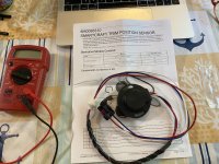
I got the new trim sender and will connect it today. Before I do that I wanted to see if I could figure out the electronics within by probing the 3 wired with my ohm meter.

IMG_3369.JPG
.
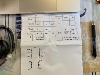
The results were not conclusive, and it appears as though there may be some diodes in the circuitry as opposed to a simple potentiometer.

Here are the results from testing the sets of leads in both directions.
.
IMG_3368.JPG
.
As you can see I got a resistance measurement with the blue wire on '+' and the White and Red wires on '-' (individually). No other combinations showed resistance/conduction.

So, maybe I'll have to take the bad one and dissect it to see what's within.
 

alldodge

Moderator
Staff member
Joined
Mar 8, 2009
Messages
42,555
My understanding is its digital and the reason Merc said i needed a A to D converter
 

tpenfield

Moderator
Staff member
Joined
Jul 18, 2011
Messages
18,138
Update: Diacom Data . . .

I brought my computer out to the boat this AM.

there seems to be 2 places to connect the cable:

1) at the engine . . . using adapter 94029 (OBD-M)
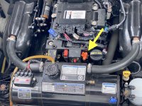
IMG_3399.JPG

.
and
2) at the Helm Station using 94029 + 94032 adapters.
.
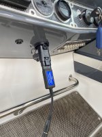
IMG_3398.JPG

.
Naturally, I tried both. Connecting to the engine got less data than connecting at the helm.

Also, @muc The engines have PCM-112 controllers, not the PCM-09. Not sure if there is much difference or not.
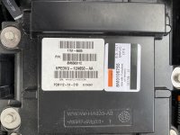
IMG_3378.JPG
.
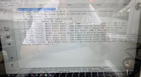
Anyway - connecting to the engine showed the trim sensor fault code (even though I connected a new properly adjusted trim sensor to the harness)
and a bunch of other fault codes.

I cleared the fault codes, but the vesselview still did not like it.

I took some screen shot from both types of connections.. I assume the one at the helm, using the multiple adapters is the correct place to connect, since it got more engine data.

I'll post the screen shots below . . .
 

tpenfield

Moderator
Staff member
Joined
Jul 18, 2011
Messages
18,138
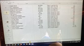
Here is the Screen shot of the engine data, connecting directly to the engine . . .
.
IMG_3376.JPG
.
Here are the fault codes that showed up.
.
IMG_3370.JPG
.
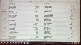
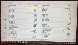
Using the helm connector and the 94029 + 94032 I got more data and no fault codes.IMG_3402.JPG
.
IMG_3403.JPG
.
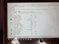
The fault history showed some issues from the past, but no current faults.
IMG_3388.JPG
.
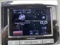
The vesselview was still cranky though . . .
.
IMG_3404.JPG
.
IMG_3405.JPG
.
So, the best that I can tell is that the voltage to the engines are fine, but somehow the vesselview is not thinking the same.

I also ran the port engine and took some screen shots, but I am not seeing any difference in the data.

TIA for any help on this. I can run a recording and share the file if anyone would like.
 

alldodge

Moderator
Staff member
Joined
Mar 8, 2009
Messages
42,555
So, the best that I can tell is that the voltage to the engines are fine
I'm on the other side of that one. Motor running

Helm it shows 12.8 system and 11.5 Bat

Engine 13.2 Ignition 12.15 Bat
 
Top