3.7L 180HP rebuild with pics!

Status
Not open for further replies.

solar7647

Lieutenant Junior Grade
Joined
Apr 23, 2009
Messages
1,218
Ok well I am doing a refit of my boat and a full rebuild of my engine. I need to because of sloppy cylinders. Now I have done a lot of research on the 3.7L/470 Merc and found lots of info but nothing with any detail to rebuilds or fixes, so I have decided to do it my self so maybe it will provide someone else with some info they need.

I have purchased a re-maned long block, it comes with a new cam, re machined crank and all new piston assemblies and a re machined head. This was all pre-assembled by the machine shop with everything to it right torque and all the difficult seals in place such as the oil seals for the crank and so on. It also comes with a new oil pump.

with the reman of this engine it comes preped for the Merc updates so if your rebuilding an early model additional parts are needed but later models should already have what is needed.

I will also be doing some mods that through my research I found make a big difference.

So lets go!
 

solar7647

Lieutenant Junior Grade
Joined
Apr 23, 2009
Messages
1,218
Re: 3.7L 180HP rebuild with pics!

The first thing to do was take care of the head. Now it comes with the factory stamped steel rockers. I have chosen to update these to full roller aluminum rockers reasons being that stamped steel rockers flex and it tends to get worse over time and as they heat up. Aluminum rollers Rockers do not so they are more efficient. They also decrease stress on the lifters and cam and regain the lost power that the head takes up.

The stock ratio of the rockers is 1.73. I purchased Scorpion full aluminum roller rockers of the same ratio, it is important that the ratio is the stock size, if not further modifications will need done. It is also important to note that they are pedestal mount so rollers where though to find for a good price. The killer is they came in a set for a V8 so now I have 8 extra.

*note: The roller Rockers are taller and will need a spacer for the valve cover.

The factory rocker set up:
picture.php


The new Rollers- they sure are purty for something hiden and covered in oil all their life!
picture.php


*update
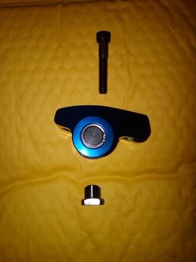
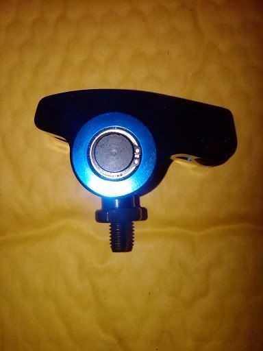
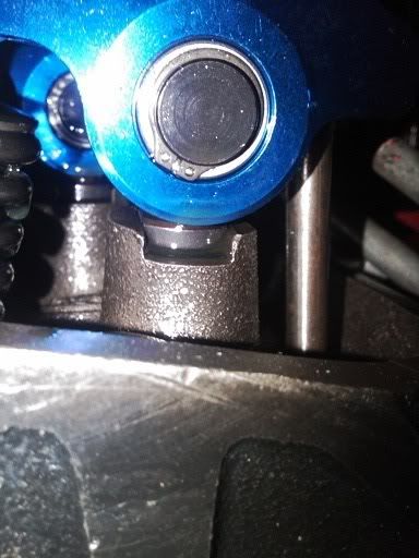
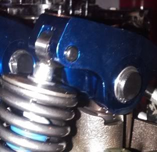
I have been getting questions on how the roller rockers mount to the head, so I am adding photos to the post to show how they work.

The rocker in its three parts
IMG00349-20100422-1249.jpg


The rocker assembled
IMG00350-20100422-1249.jpg


The rocker mounted to the head
IMG00351-20100422-1250.jpg

IMG00352-20100422-1250.jpg
 

solar7647

Lieutenant Junior Grade
Joined
Apr 23, 2009
Messages
1,218
Re: 3.7L 180HP rebuild with pics!

Next I jumped to the underside. The new oil pump and the oil pick up tube needed installed.

Now this is a part that if the time is taken it saves time and head ache later. The oil pump is driven by the distributor and needs to be aligned so that there is no binding. There is a Merc recommended tool to align the pump but the distributor can also be used to align it and that is how I did It.

The first step is to set the new long block and the donor engine both to Top Dead Center. Once both are at TDC remove the cap to the distributor and using a marker draw a line on the shaft of the distributor and the body of the distributor. This will allow the distributor to be to be aliened correctly in the new block for the TDC position making it easy to time if any adjustment needs to be made at all.

Installing the distributor in the new block is next, put on a new gasket and as it is slid into place make sure that the has line that was made lines up correctly as it is put in place. Now that the distributor is on place bolt it down.

Next is putting the oil pump in. Install the oil pump so that the shaft from the distributor slides in smoothly, and screw in bolts making sure that it is left loose, before the oil pump bolt are torque down be sure to ensure the distributor shaft is not binding in the pump. Once the oil pump is firmly attached, turn the engine over by hand to verify that the shaft to the distributor is spinning the oil pump freely.

Now the ?old? model 3.7/470 have an aluminum oil pump and later ones have a cast cast oil pump this is important to know because, if going from an aluminum to cast oil pump a new oil pick up tube is needed because they are different lengths and can?t be interchanged. Because I have a late model engine that is being rebuilt that had a cast oil pump my pick up tube was the right size and was no problem installing in the new cast oil pump. Once the pickup is in the pump it is anchored to one of the crank shaft bearing caps.
To top it off the oil pan was cleaned first and then installed. The oil dip stick will come later.


The oil pump: if you look close you can see the hex distributor shaft coming into it from the other side
picture.php


the pick up
picture.php


The hole assembly
picture.php


the oil pan
picture.php

picture.php
 

pcmpete

Petty Officer 1st Class
Joined
Apr 24, 2009
Messages
328
Re: 3.7L 180HP rebuild with pics!

where did you get the rockers? and do the standard length pushrods work?
 

solar7647

Lieutenant Junior Grade
Joined
Apr 23, 2009
Messages
1,218
Re: 3.7L 180HP rebuild with pics!

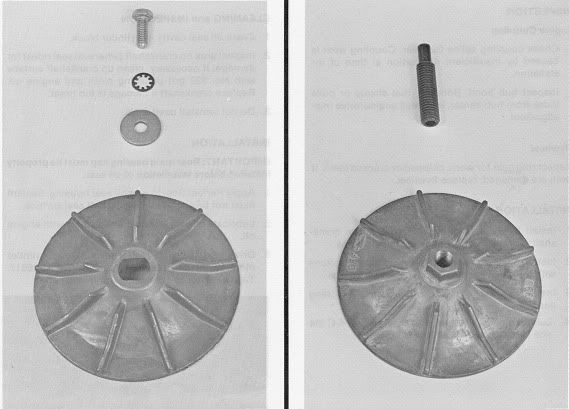
The next step was to take care of the water pump. Again this is an area where changes were made between early and late models of this engine. The early models have a bolt holding on the impeller and the late models have a stud that the impeller is spun on to.

impeller.jpg


As far as I could find out this is in relationship to the cam and cannot be switched without also changing the cam. Through my readings it seems this change was made to help with the issue early models had with the oil seal for the cam breaking down and allowing coolant to leak into the oil.

This rebuild is a late model so it has the stud system and was very easy to do. The stud is installed into the cam using an allen wrench and the impeller is spun on by hand and then tightened down using an open ended wrench.
You can see in the picture, the impeller has a nut molded on the end so that it can be tightened. You can also see the stud becomes flush with the end of the impeller when completely on.

Then the cover is installed with a new gasket. I found that an alternating pattern works best when bolting on the cover; this allows the cover to go on even and prevent any coolant leaks.

Note: You can also see the stator in the photo, this is because the photo was taken later, and the cover cannot be installed with the stator on because there is a bolt behind the stator for the cover.


picture.php


picture.php
 

solar7647

Lieutenant Junior Grade
Joined
Apr 23, 2009
Messages
1,218
Re: 3.7L 180HP rebuild with pics!

The stator and harmonic balancer are next on the list. I choose to stay with this system because there are no issues with mine, you can see in the photos the stator is clean and all the magnates in the harmonic balancer are there with no damage. The voltage regulator is also good witch is usually the problem that leads to a conventional alternator kit that can be installed to replace the stator system if wanted.

To start off the harmonic balancer and stator needed removed from my donor engine. To do this the single bolt that is in the center must be removed. Once the bolt is removed a conventional Bolt puller can be used to pull the balancer off instead of the Mercruiser tool listed in the manual. After the balancer is off the stator is removed from its mounting that it is held to by five small bolts.

Both the stator and balancer should be inspected and clean before reinstalling on the block. A bad stator will show signs of corrsion on the copper coils and and bad balancer will be missing magnets or have chips and cracks in the magnets. If this is the case they should be replaced.

The stator must be mounted first making sure that the wires are against the block, there is a small notch in the casting of the block that is meant for the wires to rest in. Once that stator is in place the harmonic balancer goes on. There should be a key way and key in the crank shaft that will only accept the balancer to slide on one way. Apply lube to the hole the crank slides into and nce the balancer is slid on by hand as far as it will go, there are several options for getting on all the way. The First is using the installation tool (info can be found in manual) or as I did using a longer bolt that has the same thread size as the bolt that holds the balancer on and a spacer and washer. I slid the spacer onto the bolt, then the washer and threaded into the end of the crank shaft. The further it is threaded in it will apply force to the balancer and slide it into place. Once I got it far enough on that I could switch to the permanent mounting bolt I did and used that to finish it up and torque it down.

*Note: The balancer will want to rotate as it is bolted on.


The stator
picture.php


Stator on new block
picture.php


The balancer showing the magnets- as you can see its in great shape
picture.php


Balancer on- mark is just past TDC because I turned it while installing the bolt that hols it on.
picture.php
 

solar7647

Lieutenant Junior Grade
Joined
Apr 23, 2009
Messages
1,218
Re: 3.7L 180HP rebuild with pics!

The next thing that was done was installing the fuel pump. I again choose to stay with the old one rather then update to an electric because the mechanical pump has never given me problems.

To remove the pump from the donor engine the two mounting bolts on ether side of it are removed. Depending on the pump it may have a spacer or may not, this is dependit on the pump arm, some are longer then others and require a spacer. The pump in use for my engine needs a cardbord gasket that is about a 1/4" thick as a spacer. This allows the pump arm to sit against the cam properly.

Once the pump is removed it was cleaned and inspected, The pump can be disassembled and rebuilt with a new gasket set.

fuel pump
picture.php


The oil filter assembly can also be done at this time. This is a feature that will very depending on the HP rating of the engine. If the engine is equiped with a 4bbl carb it will have an oil cooler all other models the oil filter will mount to the block.

The engine being rebuilt is 180Hp and is equiped with an oil cooler that is located in the intake manifold. This requires the filter to be mounted in a hanging position so that oil can be routed to and from the cooler. The assembly that does this uses a pipe bolt and mounts to the side of the block in the same location that the oil filter would be in lower Hp models. Once the assembly has been removed from the donor engine it was cleaned inspected and a new gasket was installed before attaching to new block.


Oil filter assembly
picture.php


entire side of engine, with pump, oil filter assemble and distributor (and kids crap taking up space in garage:))
picture.php
 

solar7647

Lieutenant Junior Grade
Joined
Apr 23, 2009
Messages
1,218
Re: 3.7L 180HP rebuild with pics!

where did you get the rockers? and do the standard length pushrods work?

I found them at fastengineparts.com. They where $250 a year ago when i bought them. I ran them all last season and I could really tell the difference and yes the standard push rods work.

You can find other kinds if you search "1.73 ratio roller rocker pedestal mount" on google
 

zbnutcase

Commander
Joined
Sep 19, 2009
Messages
2,055
Re: 3.7L 180HP rebuild with pics!

Those rockers and your whole engine would work better with an Edelbrock aluminum head (#60669) clamped on with half a set of 460 Ford ARP head studs. End of head gasket probs and +20hp or so to boot. Only minor machine work for front water tube needed to install. 'nutcase
 

solar7647

Lieutenant Junior Grade
Joined
Apr 23, 2009
Messages
1,218
Re: 3.7L 180HP rebuild with pics!

Those rockers and your whole engine would work better with an Edelbrock aluminum head (#60669) clamped on with half a set of 460 Ford ARP head studs. End of head gasket probs and +20hp or so to boot. Only minor machine work for front water tube needed to install. 'nutcase

I read alot about aliminum heads and the added power they provide but just cant justifiy the price. I only use the boat for fishing and family fun so the 180hp is enough. Plus I figure the new remaned head will give a much better performance then the old one that as far I know hasnt been touched since it came of the line.

Believe me it was tempting but just not in the cards this time!
 

85imperial

Cadet
Joined
Mar 2, 2010
Messages
11
Re: 3.7L 180HP rebuild with pics!

Working on a rebuild and thought about roller rockers but not really in the budget. Can the stock ones be cleaned and reused ? Do the roller rockers bolt right on ? No modifications? Can the orginal pushrods be used ? Do you still have the rest of the set ?
 

solar7647

Lieutenant Junior Grade
Joined
Apr 23, 2009
Messages
1,218
Re: 3.7L 180HP rebuild with pics!

Working on a rebuild and thought about roller rockers but not really in the budget. Can the stock ones be cleaned and reused ? Do the roller rockers bolt right on ? No modifications? Can the orginal pushrods be used ? Do you still have the rest of the set ?

Yes your origionals can be cleaned and re-used -but they must go back in the same position and with the same pushrods because as the pushrods push up on the rocker it can creat wear at the interface with the lifter and the inerface with the rocker and if you mix them up it could cause binding and damage because the wear on the two parts wont match up.

Yes the roller rockers bolt right on and yes the origioinal pushrods will work as long as they are not damaged or dont have wear and the roller rocker is the same ratio as the origional.

The photo shows three push rods not from 3.7L, but i found it online and it shows how pushrods begins to wear.

The top is good- nice and round

The bottom is begining to wear and you can see a point beginging to form

The middle one is bad wear and a point is very noticable.

picture.php


Yes I have the rest of the set.
 

solar7647

Lieutenant Junior Grade
Joined
Apr 23, 2009
Messages
1,218
Re: 3.7L 180HP rebuild with pics!

Got the voltage regulator and power steering pump on. Both very easy. They bolt right on. The only issue I had was the machine shop re-cut the treads for the holes that the studs that hold the power steering pump on so the ones from my old engine didnt fit. I was able to contact the machine shop and they were able to let me know what size the thread was so I went and got some bolts for it in stead of studs.

Voltage reg
picture.php

New bolts
picture.php

Complete pump with belt installed
picture.php
 

solar7647

Lieutenant Junior Grade
Joined
Apr 23, 2009
Messages
1,218
Re: 3.7L 180HP rebuild with pics!

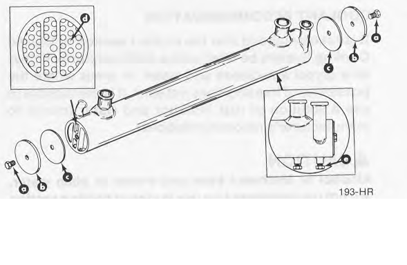
The heat exchanger is next. The first part to install is the mounting bracket, it bolts to the side of the block using 3 studs. The bracket has a radius to it so that it forms to the heat exchanger, once the bracket is mounted the exchanger tube is attached to it using two "U" bolts that go around the tube and hold it to the bracket.

Heat-exchanger
heatexchanger.png

Mounted
picture.php


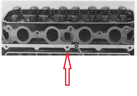
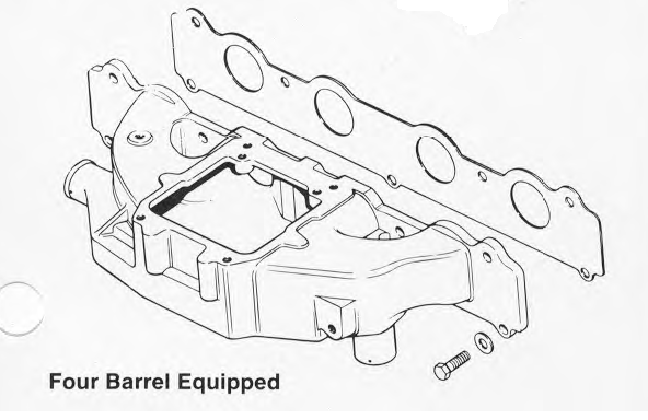
The intake is mounted to the block and the head of the motor. The top four bolts are in the head and the lower three bolts are attached to the block. The gasket for the intake, can be pron to leaks and a possible location for coolant to leak into the oil, because the gasket seals of the coolant ports for the head, the oil for the lifter area and the intake chambers it is important that the intake is mounted correctly.

The first step is to hold the gasket in place a screw the bottom center bolt in a few turns, this will help hold the gasket in place when installing the intake.
intakemount.png


The hole in the center bottom of the intake is only half closed so that the bolt that was screwed into the block can slide into intake, allowing the intake to rest on it but without the need to remove the bolt from the block.

Once the intake is resting on the bottom center bolt, the next bolts to install are the corner bolt. Starting with the top corners install the bolts and give them a few turns each, once that is done install the two top center bolts.

After all the bolts are in and it is confirmed that they all go through the gasket properly hand tighten them and then torque them to 25 ftlbs in 10 ftlb increments starting with the center top, then center bottom, then outer top and outer bottom. This help insure that the gasket has an even seal all the way across and help prevent any leaks.

It is not necessarily to remove the carb from the head if no work needs to be done to it. It will not be in the way of the bolts.

Intake
intake.png

Intake mounted
picture.php


Once the intake is mounted the lines for the oil cooler can be install. The oil cooler is cut into the bottom of the intake with a cap bolted to the bottom of the intake to cover it. The lines for the cooler run from the oil filter and screw into the cap and the return the oil back to the engine.

oil cooler lines
picture.php
 

solar7647

Lieutenant Junior Grade
Joined
Apr 23, 2009
Messages
1,218
Re: 3.7L 180HP rebuild with pics!

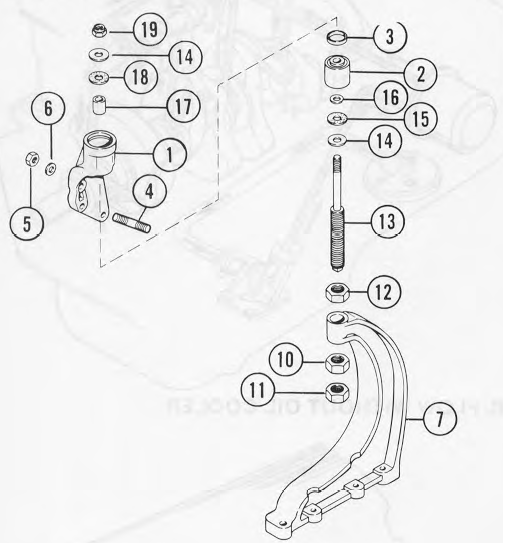
Now that so much is mounted to the new block it is getting heavy and I dont trust my stand, it was a cheap HF one and is rated to hold the weight of the entire engine but I am not risking it, the rest of the parts are heavy so I installed the front motor mount so that I could lift it with the engine crane and then mounted the fly wheel, coupling and flywheel housing so it can sit on the ground for the rest of the rebuilt.

The front mounts is held on with three studs and I removed it from the old engine in one piece but had to take it apart to bolt in on the new block. It comes apart by taking the top nut off, the bottom part just slides out then. There are washers and spacers in there though so i was careful not to loose them.

The mount bolted on
picture.php


The mount re-assembled on the new block
picture.php


The mount and all the parts for it
mount.png
 

solar7647

Lieutenant Junior Grade
Joined
Apr 23, 2009
Messages
1,218
Re: 3.7L 180HP rebuild with pics!

The last thing I did for the day was put the flywheel, coupling and flywheel housing on the new block.

The flywheel is held on by 6 bolts, but it only goes on one way. There is a dot stamped into the flywheel right next to one of the holes for the bolts, that hole lines up with the number 1 stamped into the end of the crank shaft. The holes will not line up any other way.

The flywheel
picture.php


The coupling also bolts on with 6 bolts into the 6 holes on the flywheel, and are torqued down. I didnt get a pic of the coupling before i put the housing on sorry. do have one of it with the housing on though.
picture.php


The housing is held on with 4 bolt not counting the bolts that hold the starter on. As you can see in the pic the new engine is sitting safely on the ground.

picture.php


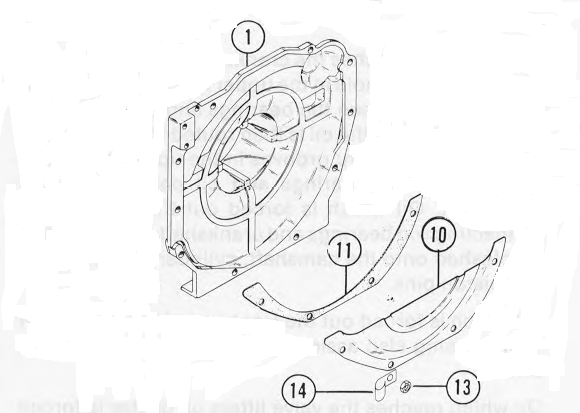
There is also another flywheel cover that sits between the oil pan and the fly wheel, now that the flywheel housing is on this cover can also be mounted. It is held on using four bolts and needs a gasket installed. The Gasket helps protect the fly wheel from any liquids that may get into the bilge. This cover is seen below as number 10. This cover is bent easily and if mis-shaped and rub the flywheel giving a metal knocking noise so it is important not to damage it during installation.

flywheelhouse.png
 

solar7647

Lieutenant Junior Grade
Joined
Apr 23, 2009
Messages
1,218
Re: 3.7L 180HP rebuild with pics!

I moved to the started next because it is alot easyer to put on without the exhaust manifold on. The starter bolts on with 6 bolts including the two for the mounting plate. The first two go through the flywheel housing and bolt the starter to the housing. The next two hold the mounting plate to the block and the last two hold the starter to the mounting plate keeping it level. I have found that the easyest way to install the starter is to bolt to the housing first, then install the mounting plate and last bolt the starter to the mounting plate.

the bolt locations
picture.php


Better shot of the mounting plate
picture.php
 

solar7647

Lieutenant Junior Grade
Joined
Apr 23, 2009
Messages
1,218
Re: 3.7L 180HP rebuild with pics!

The exhaust manifold bolts to the head using three studs and four long bolts and requires a metal gasket.

The head on the new long block did not come with studs for this so I had to remove them from the old engine first. Using a pipe wrench to gab hold of the studs, they can be turned so that they came be removed from the head. I then coated the treads with anti-seize and reinstalled them into the new head.
The studs in the new head
picture.php


The next step was to install the metal gasket. Slide the gasket over the studs so that it is held in place. The allows the hands free to install the manifold.

Once the gasket is in place the manifold slides onto the studs. It makes it easyer if it is kept level and straight as it is slid on so that there is no binding of the studs in the holes in the manifold.

The first bolt to install is the last one or the one all the way to the right. This allows the manifold to be supported on both ends and helps line up the gasket holes with the holes in the manifold and head. If not done this way I have found that the bolts will be hard to line up with the hole due to the manifold is sagging at the end. once the manifold is on and the bolt are in you only need to torque down the bolts, the studs will hold the shift assembly when it is installed in the boat.
The manifold on
picture.php


Once the manifold is on, the coolant hoses and the cooler for the power stearing fluid can be installed.

Hoses and power stearing fluid cooler on
picture.php
 

Bob_VT

Moderator & Unofficial iBoats Historian
Staff member
Joined
May 19, 2001
Messages
26,064
Re: 3.7L 180HP rebuild with pics!

Very nice work. I had a 3.7 that I worked on. I wish I had that kind of access to those darn starter bolts! ;)

You will have a real reliable engine to play with!
 

badkins50

Senior Chief Petty Officer
Joined
Sep 20, 2009
Messages
676
Re: 3.7L 180HP rebuild with pics!

Great information 7647. I have a 1984 470 170hp 3.7L in my boat. Great information to have for a future winter project. Thanks.
 
Status
Not open for further replies.
Top