Electronics question

i386

Captain
Joined
Aug 24, 2004
Messages
3,548
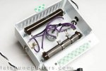
Can someone identify the parts in this pic?

This is what I think I see...

It's a switch, a 1/4" mono phono jack, and 2 "special" resistors.

The top resistor has a single unknown value.
The bottom resistor is "tapped?" for 3 separate values.
The switch has 4 positions.

Is position 4 just the big resistor or both? Series or parallel? Better yet, can someone draw a schematic (minus the values or course).

I'll take whatever I can get. Thanks!
 

Attachments

  • brake_lite4_lg.jpg
    brake_lite4_lg.jpg
    33.9 KB · Views: 0

ThumbPkr

Petty Officer 1st Class
Joined
Aug 17, 2007
Messages
371
Re: Electronics question

1/4" phone jack,two 10 watt or greater wirewound resistors,one with two variable taps on it.......I cannot tell if the switch is a pot and switch or if it is all switch and I could draw a schematic if I had it in my hand to look at and put a meter on it.It looks like an variable attenuator controlled by the rotary switch.What is it??LOL.Ron G
 

i386

Captain
Joined
Aug 24, 2004
Messages
3,548
Re: Electronics question

1/4" phone jack,two 10 watt or greater wirewound resistors,one with two variable taps on it.......I cannot tell if the switch is a pot and switch or if it is all switch and I could draw a schematic if I had it in my hand to look at and put a meter on it.It looks like an variable attenuator controlled by the rotary switch.What is it??LOL.Ron G

Yea, that's exactly what it is.


I was just wondering if it was something I could build it myself. This is but a single part of some stuff I've been researching lately. It involves low-wattage guitar tube amplifiers if anyone's interested in the discussion.
 

Xcusme

Commander
Joined
Apr 21, 2003
Messages
2,888
Re: Electronics question

Whatcha working on?? Looking to build one?
 

i386

Captain
Joined
Aug 24, 2004
Messages
3,548
Re: Electronics question

Whatcha working on?? Looking to build one?

It's an attenuator for a guitar amp. This one:


I happened upon a pic of its innards and thought it might be pretty simple to build. The price of the store-bought one is about $169. I was just wondering what I could build one for.

I don't know what value the resistors are. I don't know where to buy them either. I do know the device can handle up to 45watts but no more. Each click should increase the resistance. I could use my meter and some jumpers to make sure it's wired right before I started soldering. I guess the components need to be of pretty high quality too since an audio signal is running through them.

What's this all about you ask?

Tube guitar amplifiers sound best when they're cranked. The "magic" happens when the tube(s) in the power amp section are saturated. The problem is trying to accomplish this at a reasonable volume level. Most people don't understand that a small 15Watt amp is LOUD. Even 1watt is loud. I'm sure the folks that make amps understand this, but the people that buy them don't. It's hard to find an affordable high-quality low-watt tube amp. When you do find one, they're bare bones and no features. The attenuator is one way to lower the perceived volume of a cranked amp so that's why I'm looking into it.
 

ThumbPkr

Petty Officer 1st Class
Joined
Aug 17, 2007
Messages
371
Re: Electronics question

If you have an ohmmeter you can very simply determine the values by connecting one lead to the center conductor of the input jack and the other lead to the center conductor of the output and measure the readings for each switch position.You won't even have to open it up for that.
If you want to measure each resistor value and each tap connect one lead of the ohmmeter to the center conductor as before and work your way from 0 ohms progressively to the output and the sum of each measurement should equal the total of the heighest reading that you got from input to output.
Tell me what the readings are and I will draw a schematic for you.
Parts are plentiful and cheap,you can buy the box at RS to mount it in.
My amp is a Peavey "Artist 240" with two channels and using the footswitch you can run the channels on parallel or series.You can therefore saturate or distort the signal or get incredible sustain by over driving the signal at any volume you may choose by controlling the master volume at whatever level that you can live with.
Unfortunately that capability goes mostly to waste as I like a nice clean signal for my Country Gentleman and my digital echo and that Peavey will bring you to tears.LOL.
If I can help you locate parts.........surplus or hobby electronics suppliers are the way to go,let me know.Ron G
 

i386

Captain
Joined
Aug 24, 2004
Messages
3,548
Re: Electronics question

If you have an ohmmeter you can very simply determine the values by connecting one lead to the center conductor of the input jack and the other lead to the center conductor of the output and measure the readings for each switch position.You won't even have to open it up for that.
If you want to measure each resistor value and each tap connect one lead of the ohmmeter to the center conductor as before and work your way from 0 ohms progressively to the output and the sum of each measurement should equal the total of the heighest reading that you got from input to output.
Tell me what the readings are and I will draw a schematic for you.
Parts are plentiful and cheap,you can buy the box at RS to mount it in.
My amp is a Peavey "Artist 240" with two channels and using the footswitch you can run the channels on parallel or series.You can therefore saturate or distort the signal or get incredible sustain by over driving the signal at any volume you may choose by controlling the master volume at whatever level that you can live with.
Unfortunately that capability goes mostly to waste as I like a nice clean signal for my Country Gentleman and my digital echo and that Peavey will bring you to tears.LOL.
If I can help you locate parts.........surplus or hobby electronics suppliers are the way to go,let me know.Ron G

I could do that if I had the device in my hand. But then I wouldn't need to build one.;)

BTW, the idea behind using one of these is that (good/desirable) distortion comes from 3 places.

1. Preamp section. That's controlled by the gain setting.

2. Power amp section. This only occurs when the master volume is really high.

3. When the speaker itself begins to distort.

** 2&3 share a special relationship.

The attenuator helps to accomplish #2 without having the amp so loud.
 

ThumbPkr

Petty Officer 1st Class
Joined
Aug 17, 2007
Messages
371
Re: Electronics question

I thought the objective was to own one for less than the price you quoted.
There is no way to draw a meaningful schematic without any values for the components.Ron G
 

Adjuster

Petty Officer 1st Class
Joined
Aug 27, 2008
Messages
233
Re: Electronics question

Not to get off topic but you mentioned how loud one watt is. I was recently reading up on this very thing in regards to speaker efficiency. One watt of pure sound is 100 decibels measured at a distance of 10 feet. Speakers are extremely inefficient. Thats why you have 35 watt stereos and 100 watt speakers and so on. A stereo has to put out large wattage to get a speaker to respond. An amplifier may put out 50 watts but the speaker can only produce 1 watt of it as sound. The rest is lost energy. I don't know where it goes.

Disclaimer:
I am not a scientist.
I read this on the internet.
All given values are questionable.
I don't do drugs but I drink.
I am not drinking now.
I may have been drinking when I read this information.
 

Adjuster

Petty Officer 1st Class
Joined
Aug 27, 2008
Messages
233
Re: Electronics question

I read through some of that. Makes me wish I was smarter. But it does show the amazing inefficiency of speakers.
 
Top