Foot Control jimmy rig set up.... minn kota power drive V2 50 pd

chevydan04

Cadet
Joined
Apr 9, 2010
Messages
19
Ok guys, so I have written Minn Kota a nasty letter about their poor engineering of the foot pedal on the V2 trolling motors. Basically the magnetic strip they use is highly prone to wearing, (I believe prematurely), Plus the pedal alone cost $65-$100.

Well I figured out a way to get constant %100 power out of mine and that was by connecting the two wires that come out of the magnetic strip.

But I want to make my own type of speed regulator...

Any ideas on how I can do this?

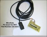
I will include a picture of a similar control board, the magnetic strip is the long leach looking part on the circuit board. It has two wires connecting to it.
 

Attachments

  • 598.jpg
    598.jpg
    41.9 KB · Views: 1

Silvertip

Supreme Mariner
Joined
Sep 22, 2003
Messages
28,771
Re: Foot Control jimmy rig set up.... minn kota power drive V2 50 pd

Got some news for you sir. That is not a magnetic strip. The white strip is conductive on its underside. The dark strip beneath it is NOT magnetic --- it is a resistive element. When you move the slider on the foot pedal, you move the contact point between the white element and resistor which varies the resistance. Changing the resistance changes the input to the electronic motor control circuit which changes the pulse width going to the motor which ultiimately controls its speed. At full forward on the slider you get full power to the motor. Besides, the foot pedal already has a constant on switch and moving the slider forward provides full power. Before you cost yourself a new foot pedal, I suggest you understand what you are dealing with. Or better yet, leave it alone. I've never had a MinnKota foot pedal fail but I've seen failed units due to neglect (dirt, leaves, constant wet) from not covering the boat.
 

chevydan04

Cadet
Joined
Apr 9, 2010
Messages
19
Re: Foot Control jimmy rig set up.... minn kota power drive V2 50 pd

The trolling motor has always lived in the garage, never left in the elements.
In DE it is all that I ever use because all the lakes are no wake lakes, it has been used quite a bit in two seasons of use.

Do you know of a alternate part I could use to create the various resistance I would need to control the speed of the motor.

the sliding feature was all ready ruined due to a poor design.

Also read others posts about minn kota's on this web site, read cabelas customer reviews on the foot controllers. people will replace them 3 times in 2 years....


http://www.cabelas.com/cabelas/en/templates/product/reviews.jsp?productid=017610


I eliminated the resistive strip in my foot pedal, now I want to put a new type of resistor or variable resistor in its place, any ideas?
 

Silvertip

Supreme Mariner
Joined
Sep 22, 2003
Messages
28,771
Re: Foot Control jimmy rig set up.... minn kota power drive V2 50 pd

Not knowing what the resistance of the dark resistor is you don't know what you need. So step 1 is to measure it (out of circuit). Step 2 would be to go to Radio Shack and buy a potentiometer with the required resistance. One end of the pot connects to one end of the resistive element and the center terminal connects to the other. You MUST disable the resistive element or you will resistance in parallel which will hose the speed control. Will this work? Probably! Can I guarantee it will? NO! Why? Because I have no idea what skill set you have dealing with soldering, selecting components, and assembling them. Potential problems would be that a potentiometer is not hermetically sealed and would be junk in a heartbeat if wet. Find one that is water tight and you may have a workable system. As for MinnKota issues, some folks are simply tough on their stuff. Other folks run the same equipment for years with no issue. The same applies to cars, trucks, bicycles and airplanes.
 

TerryMSU

Senior Chief Petty Officer
Joined
Jul 31, 2007
Messages
743
Re: Foot Control jimmy rig set up.... minn kota power drive V2 50 pd

Silvertip is 100% correct. Keep it clean. I take mine out of the boat whenever I am not using the boat and then I store it indooors. You might try some contact cleaner on it which can be purchased at a good electronics store (not likely Radio Shack). Also, there is almost certainly a moving contact on that part. Make sure it is making contact with the black strip (or perhaps the gray strip). Yours does not look like one that failed due to use (unless you did a lot of cleaning on it). Make sure it is clean and try putting it back together. If you are lucky and you did not damage something else in the process maybe it will work.

TerryMSU
 

chevydan04

Cadet
Joined
Apr 9, 2010
Messages
19
Re: Foot Control jimmy rig set up.... minn kota power drive V2 50 pd

the picture I posted was not of mine. It is a similar design from a different minn kota foot pedal. I used it for reference only.

I am good at soldering.

I called minn kota found out the resistance at 0 is 30 ohms and at 10 is 830 ohms.

So my idea is to insall a potentiometer of some sort.

I appreciate your replies

Also if minn kota would have used a roller type magnet system instead of a straight dragging over the contact strip the wear would not be so bad...

When I get a chance i will take a picture of mine.
 

4JawChuck

Chief Petty Officer
Joined
Aug 7, 2009
Messages
504
Re: Foot Control jimmy rig set up.... minn kota power drive V2 50 pd

I have the same opinion of the foot controllers...junk. The other alternatives are more expensive, you get what you pay for. Look for IP66 spec potentiometers in the ohm range you require, you may have to wire in the proper amp rated resistors to get a pot with the range you desire...its never simple. Infinite speed adjustability is over rated, there is nothing wrong with 10-20 speeds selected via button control with inline resistors if you wanted to keep it cheap...probably more durable too.

Here is a guy who modified one for a submarine who faced the same problem, hope it helps.

http://www.submarineboat.com/thrusters.htm
 

TerryMSU

Senior Chief Petty Officer
Joined
Jul 31, 2007
Messages
743
Re: Foot Control jimmy rig set up.... minn kota power drive V2 50 pd

the picture I posted was not of mine. It is a similar design from a different minn kota foot pedal. I used it for reference only.

I am good at soldering.

I called minn kota found out the resistance at 0 is 30 ohms and at 10 is 830 ohms.

So my idea is to insall a potentiometer of some sort.

I appreciate your replies

Also if minn kota would have used a roller type magnet system instead of a straight dragging over the contact strip the wear would not be so bad...

When I get a chance i will take a picture of mine.

Dan:

This is not a magnetic system. This connection is part of a resistor. The electrical contact is absolutely necessary and for it to be varaible, it must be moveable. Think of it as more like a switch except variable as to where the contact is located at. The variable (moveable) contact is required. By the way, you are not using this in saltwater, right? The unit is not designed for salt water. Salt water is a VERY nasty environment electrically.

Given the above , I would try a 1K ohm potentiometer. You will want to use the center and one end as the two contacts. I would look at a wirewound pot with at least a 1/2 watt power rating. Pots are also rated for the number of operating cycles (rotations).

You could also try a rotary switch with smaller resistors between the terminals. Stepped values (100, 200, 300, 400 ohms, etc.) between the terminals and common could work. The rotary switch would give the best reliability and you can probably put some dielectric grease on the contacts.

TerryMSU
 

John_S

Rear Admiral
Joined
Jun 21, 2004
Messages
4,269
Re: Foot Control jimmy rig set up.... minn kota power drive V2 50 pd

At this point, I don't see an easy way that this will be fixed such that it will be easy to use and not need allot attention (outside of a direct replacement part), or be any more reliable than the production switch. ie after finding components that can withstand the wet, you will have to modify the current foot case or make a new one.

Doesn't MK sell a wireless kit for these series of trollers? While I bet it is not cheap, it would get you away from pots, and still keep a production look/feel to it. Just another option to consider.
 

Silvertip

Supreme Mariner
Joined
Sep 22, 2003
Messages
28,771
Re: Foot Control jimmy rig set up.... minn kota power drive V2 50 pd

If you are hell-bent on creating a work around for this system, install a multi-position rotary switch in a water tight box, then wire the appropriate size resistors to the switch. Mount the box at the bow and via a small plug and receptacle, connect it to the foot pedal. You now have as many speeds as you want, or if you can find a potentiometer with that resistance range and that can also handle the current requirements, you have infinite adjustment just like the foot pedal had. Search Radio Shack for "potentiometers" in the range of 30 - 1000 ohms. While you may find one, it may not have the current (wattage) rating you need. I would guess a 10 watt resistor would survive in that circuit. Higher wattage individual resistors are available if you went with the rotary switch setup. Here is a diagram of what that would look like. Resistor values can only be accurate for whatever MK told you (30 on the high end, 830 on the low end). what you pick between those numbers will determine what that speed will be.

MKPDSpeedResistor.jpg
 

TerryMSU

Senior Chief Petty Officer
Joined
Jul 31, 2007
Messages
743
Re: Foot Control jimmy rig set up.... minn kota power drive V2 50 pd

Some of Silvertip's values are not "standard" values. Just pick the closest value that you can get and it should be suitable. Also, if this is just replacing the control resistor (and I assume it is), 1/4 to 1/2 watt resistors are probably sufficient. That controller merely send a signal to another device that does the real controlling. Other than that it should (hopefully) work. To verify this you can temporarily jump in the various resistors and see if the speed changes as desired.

TerryMSU
 

Silvertip

Supreme Mariner
Joined
Sep 22, 2003
Messages
28,771
Re: Foot Control jimmy rig set up.... minn kota power drive V2 50 pd

You can obtain any resistance value you need by adding resistors in series or parallel. The values I show are merely the high and low numbers MK provided. Anything in between is just a guess and trial and error will be required.
 

TerryMSU

Senior Chief Petty Officer
Joined
Jul 31, 2007
Messages
743
Re: Foot Control jimmy rig set up.... minn kota power drive V2 50 pd

You can obtain any resistance value you need by adding resistors in series or parallel. The values I show are merely the high and low numbers MK provided. Anything in between is just a guess and trial and error will be required.


True, but I doubt that he needs any real precision for this application. I assumed that he would use just a single resistor for each spot.

TerryMSU
 

Silvertip

Supreme Mariner
Joined
Sep 22, 2003
Messages
28,771
Re: Foot Control jimmy rig set up.... minn kota power drive V2 50 pd

OK -- since we have infinitely variable resistance between 30 and 830 ohms, the only given is those two numbers. What we also don't know is what happens to the actual speed control module if the input resistance goes below 30 or above 830. That would constitute a degree of precision since we don't want to "waste" the controller. What one picks for speeds 2 through 9 is still a matter of trial and error and personal preference and obviously does not require precision. In the original slider configuration we have no idea how linear speed selection is so simply dividing up the range 30 - 830 into however many speeds you want is really a crap shoot. We are pickin' knits here. Put any number of resistors on a switch with 30 ohms on one end and 830 on the other and go fishing. You will have what you have. Change resistors if it isn't.
 

4JawChuck

Chief Petty Officer
Joined
Aug 7, 2009
Messages
504
Re: Foot Control jimmy rig set up.... minn kota power drive V2 50 pd

Actually I can tell you exactly what happens when the resistance goes below 30 ohms, it fries the control board! Guess what happens when the foot control gets wet inside...it goes zero resistance and fries the control board. Guess what happens when the slider wears out or gets indented at the last point where the slider was positioned...it goes zero resistance and fries the control board! There is no lifter to take the slider off the blister adjuster on the foot control board so it fries the board eventually since the design is so poor.

Designed in obsolescence at its finest!:D
 
Top