Fuel flow chart 1984' 115hp Evinrude V4 Flat head

Pessemist

Seaman
Joined
Sep 14, 2002
Messages
61
I am just about finishing up a rebuild on my model E115TLCRD with the VRO removed.

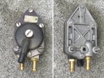
I meticulously recorded all wires, vacume lines etc but my son removed the fuel pump and didn't record where the lines went.

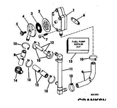
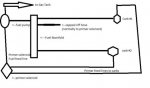
I got the line to the carbs and the line to the gas tank installed but on the side of the fuel pump there is a 8" line that I can't find any logical place to hook up (3/8" fuel hose).

It goes from the fuel pump to where?

I would think it supplies gas to the primer solenoid but it is about 5" too short to get there. The primer has 2 lines to the carbs but no line to supply gas on the bigger nipple.

Is there a schematic that shows fuel flaw for this engine?

thanks!

doug
 
Last edited:

bktheking

Vice Admiral
Joined
Jul 29, 2008
Messages
5,057
Re: Fuel flow chart 1983' 115hp Evinrude V4 Flat head

Re: Fuel flow chart 1983' 115hp Evinrude V4 Flat head

Check shop.evinrude.com, the schematic of the pump and line description are listed. If it had VRO then it's 84+, 83 didn't have VRO.
 

Pessemist

Seaman
Joined
Sep 14, 2002
Messages
61
Re: Fuel flow chart 1983' 115hp Evinrude V4 Flat head

Re: Fuel flow chart 1983' 115hp Evinrude V4 Flat head

Check shop.evinrude.com, the schematic of the pump and line description are listed. If it had VRO then it's 84+, 83 didn't have VRO.


Thank you. I looked there and the displayed fuel pump does not have this 'third' nipple coming out the side. Hence my consternation.

http://shop2.evinrude.com/Index.aspx?s1=d724d3e720d69299ec766685504b24c9&catalog_id=0&siteid=1


It has the central hose to gas tank, the bottom nipple feeding the carb manifolds and about an 8" section of fuel line off the right side of the fuel pump.

It is this 8" section of fuel hose that stymies me. I can not figure out what it connects to from the fuel pump?

Any idea?
 

Chinewalker

Fleet Admiral
Joined
Aug 19, 2001
Messages
8,902
Re: Fuel flow chart 1983' 115hp Evinrude V4 Flat head

Re: Fuel flow chart 1983' 115hp Evinrude V4 Flat head

That would be the pressure feed line. Goes to a nipple on the crankcase, down low on the port side. The oscillating pressure in the crankcase runs the diaphram in the pump.
 

Pessemist

Seaman
Joined
Sep 14, 2002
Messages
61
Re: Fuel flow chart 1983' 115hp Evinrude V4 Flat head

Re: Fuel flow chart 1983' 115hp Evinrude V4 Flat head

That would be the pressure feed line. Goes to a nipple on the crankcase, down low on the port side. The oscillating pressure in the crankcase runs the diaphram in the pump.


Is there a picture of this 'nipple' location anywhere? I look on both the old motor and the new rebuilt and I can see nothing on the low portside that a 3/8" fuel line could hook into. I don't even see a spot where a nipple could be placed so that it enters the crankcase!

Is there an exact location for this nipple?

I don't see t on any schematic for this motor as well. Or I am miss-identifying it.

thanks for help so far.
 

Daviet

Fleet Admiral
Joined
Sep 24, 2008
Messages
8,958
Re: Fuel flow chart 1983' 115hp Evinrude V4 Flat head

Re: Fuel flow chart 1983' 115hp Evinrude V4 Flat head

You can't be working on a 1983 engine, it did not have VRO on it.
By the model number you are working on a 1996 engine.
If you look at the parts breakdown for a 1996, fuel pump 90/115, you will see the pulse limiter (#4) and its location from the VRO pump. It doesn't show it on the crankcase, but maybe you can visualize where it goes to the crankcase by the shape of the hose.
 

bktheking

Vice Admiral
Joined
Jul 29, 2008
Messages
5,057
Re: Fuel flow chart 1983' 115hp Evinrude V4 Flat head

Re: Fuel flow chart 1983' 115hp Evinrude V4 Flat head

Um Scott, not so sure about that one, there is a gasket behind the pump, suspect the pump is oscillated from a hole in the center of the gasket like all the rest.

According to the diagram:

#9 hose coming off the bottom of the pump feeds "the fuel manifold" #11

From the fuel manifold, the bottom line # 12 feeds the carbs, #13 is a primer line, #8 should be feed from the fuel tank.

fuelpump.jpg


Reading back now i'm totally lost, thinking this isn't an 83, no third feed like Scott had mentioned, which would be the case if the pressure was being fed from a line instead of directly from the mounting point.
 

bktheking

Vice Admiral
Joined
Jul 29, 2008
Messages
5,057
Re: Fuel flow chart 1983' 115hp Evinrude V4 Flat head

Re: Fuel flow chart 1983' 115hp Evinrude V4 Flat head

E115TL is any year, the rest to identify the year is missing.
 

Daviet

Fleet Admiral
Joined
Sep 24, 2008
Messages
8,958
Re: Fuel flow chart 1983' 115hp Evinrude V4 Flat head

Re: Fuel flow chart 1983' 115hp Evinrude V4 Flat head

If it had a VRO and it was removed, you have to use the line from the pulse limiter to pulse the replacement fuel pump, don't you.
 

bktheking

Vice Admiral
Joined
Jul 29, 2008
Messages
5,057
Re: Fuel flow chart 1983' 115hp Evinrude V4 Flat head

Re: Fuel flow chart 1983' 115hp Evinrude V4 Flat head

Agreed
 

Chinewalker

Fleet Admiral
Joined
Aug 19, 2001
Messages
8,902
Re: Fuel flow chart 1983' 115hp Evinrude V4 Flat head

Re: Fuel flow chart 1983' 115hp Evinrude V4 Flat head

Here are picks of the two types of fuel pump hook-ups on the intake manifolds. The silver intake on the right has a nipple for the pressure feed (as a VRO motor would have), and the white intake on the left has the boss with no nipple for a direct bolt-on pump. The boss is present in both versions and it is possible to use them either way, remote pump or direct pump. It would simply require the addition or subtraction of the nipple on the intake...

If the fuel pump you're using has TWO nipples (one on the cap and one in the plastic body) then it is a direct bolt-on pump. If it has THREE nipples (on on the cap and two in the plastic body) then it is a remote pump requiring a pressure feed hose. This also assumes you're using an OMC/BRP fuel pump.
 

Attachments

  • IntakeManifold_2737.jpg
    IntakeManifold_2737.jpg
    146.9 KB · Views: 3
  • OMCFuelPump_1212.jpg
    OMCFuelPump_1212.jpg
    154.5 KB · Views: 6

Pessemist

Seaman
Joined
Sep 14, 2002
Messages
61
Re: Fuel flow chart 1983' 115hp Evinrude V4 Flat head

Re: Fuel flow chart 1983' 115hp Evinrude V4 Flat head

Here are picks of the two types of fuel pump hook-ups on the intake manifolds. The silver intake on the right has a nipple for the pressure feed (as a VRO motor would have), and the white intake on the left has the boss with no nipple for a direct bolt-on pump. The boss is present in both versions and it is possible to use them either way, remote pump or direct pump. It would simply require the addition or subtraction of the nipple on the intake...

If the fuel pump you're using has TWO nipples (one on the cap and one in the plastic body) then it is a direct bolt-on pump. If it has THREE nipples (on on the cap and two in the plastic body) then it is a remote pump requiring a pressure feed hose. This also assumes you're using an OMC/BRP fuel pump.


This is definitely a 1984 motor. Model E115TLCRD

Now I am really confused! The motor has a THREE nipples and is MOUNTED on the boss. So now I have a fuel pump bolted onto the boss and no nipple for the THIRD hose.

Here is a picture of the pump installed. The fuel line bent up is the one I don't know where it goes. It is about 8" long 3/8" fuel line. It would be the Pressure feed hose as the other Two fuel pump nipples go to the gas tank and Fuel manifold respectively.

Any ideas?

Thanks!
 

Attachments

  • fuel-pump.jpg
    fuel-pump.jpg
    12 KB · Views: 3

Daviet

Fleet Admiral
Joined
Sep 24, 2008
Messages
8,958
Re: Fuel flow chart 1984' 115hp Evinrude V4 Flat head

The hose has to hook up to the block to supply a compression pulse to operate the fuel pump. If the hoses on the pump are orginal, then the nipple has to be within reach of the hose. Take a flash light and look on the block within reach of the hose, maybe remove the fuel pump for a better view.
 

Pessemist

Seaman
Joined
Sep 14, 2002
Messages
61
Re: Fuel flow chart 1984' 115hp Evinrude V4 Flat head

The hose has to hook up to the block to supply a compression pulse to operate the fuel pump. If the hoses on the pump are orginal, then the nipple has to be within reach of the hose. Take a flash light and look on the block within reach of the hose, maybe remove the fuel pump for a better view.

On the 'Block' or on the intake manifold?

It is mounted on a rebuilt powerhead. I been over the 'old' block with a magnifying glass and there is no nipple on it. That leaves the intake manifold. I think I am going to have to take it all apart again and find it because I been peering for hours with a light and no luck and not sure where on the IM to look.
 

Daviet

Fleet Admiral
Joined
Sep 24, 2008
Messages
8,958
Re: Fuel flow chart 1984' 115hp Evinrude V4 Flat head

Lets backup a bit.
Go back and look at the pictures that chinewalker posted.
Look to the right of the lower carb mounting flange on the left picture, there is a black oval shape.
Look on the picture on the right at the same location, do you see the nipple?
That is the attachment point for your hose.
 

Pessemist

Seaman
Joined
Sep 14, 2002
Messages
61
Re: Fuel flow chart 1984' 115hp Evinrude V4 Flat head

Lets backup a bit.
Go back and look at the pictures that chinewalker posted.
Look to the right of the lower carb mounting flange on the left picture, there is a black oval shape.
Look on the picture on the right at the same location, do you see the nipple?
That is the attachment point for your hose.

Yes I see all that. The fuel pump is MOUNTED on the black oval flange. There thus is no nipple.

I believe this may be a 'custom' job and I want to run something by you guys and see if it makes sense.

The fuel manifold only has two outlets: One for each carb. There is specifically NO hose to the primer solenoid from the fuel manifold as most schematics show. (manifold outlet for it is capped off)

Since the fuel pump is mounted over the flange it presumably gets its impulse from there. Could that third hose be routed directly to the primer solenoid?

The engine ran before I rebuilt it with a new power head and if that setup I described works then I've accounted for all the hoses.

What you guys think?

Attached is a schematic. What you guys call an 'Impulse line' I marked as fuel feed for the Solenoid primer

(fingers crossed)
 

Attachments

  • schematic fuel.jpg
    schematic fuel.jpg
    14.2 KB · Views: 2

bktheking

Vice Admiral
Joined
Jul 29, 2008
Messages
5,057
Re: Fuel flow chart 1984' 115hp Evinrude V4 Flat head

You want my best guess, that line you see was never hooked up, as Chinewalker said , they can be used either way. I'd pull that hose off and cap that impulse line. As far as primer line, that would come off the manifold and be no where even close to 3/8".

Looking at your pic it's hard to tell, it looks as if that line is going to the fuel feed side of the pump, the hard plastic cap that usually says "filter" on it and is held on by a center screw.
 

Daviet

Fleet Admiral
Joined
Sep 24, 2008
Messages
8,958
Re: Fuel flow chart 1984' 115hp Evinrude V4 Flat head

If you hook up a fuel tank and pump the primer bulb does fuel come out of the third line?
 

Chinewalker

Fleet Admiral
Joined
Aug 19, 2001
Messages
8,902
Re: Fuel flow chart 1984' 115hp Evinrude V4 Flat head

You want my best guess, that line you see was never hooked up, as Chinewalker said , they can be used either way. I'd pull that hose off and cap that impulse line. As far as primer line, that would come off the manifold and be no where even close to 3/8".

Looking at your pic it's hard to tell, it looks as if that line is going to the fuel feed side of the pump, the hard plastic cap that usually says "filter" on it and is held on by a center screw.

Yeah, something isn't quite right here. Is the hole in the BACK of the fuel pump, the one that would actually receive the pressure pulse if it were bolted directly to the crankcase, an actual hole into the pump, or is it just the unmachined hole that a 3-nipple pump would have? If the hole doesn't go all the way into the pump, then it's not doing anything and the third hose would need to go to a pulse point. If it DOES have a hole into the pump, then I have no idea what the third hose does.

And yes, fuel goes IN the cap, and OUT one of the nipples on the pump body. Have you tried blowing through various hoses to see what happens? Blowing IN the IN side should result in a light buzzing sound and air flow through the pump. The buzzing is the check flappers inside. Blowing IN and OUT the pressure side would result in a slight buzz as the pump works the diaphram and check flappers. Blowing IN the OUT side should get you little, if any air flow, unless you suck back through.
 

djpeters

Lieutenant Commander
Joined
Jun 9, 2010
Messages
1,824
Re: Fuel flow chart 1984' 115hp Evinrude V4 Flat head

On my '85 Evinrude 140 there is a line coming off the fuel pump that is plugged. Last week the said "plug" fell out and the motor would not stay running. Mine has the VRO removed as well.
 
Top