Glassing in new motor mounts?

Status
Not open for further replies.

nola mike

Vice Admiral
Joined
Apr 22, 2009
Messages
5,519
I'm replacing my 3.7L with a 4.3. Next week's project is going to be to glass in some new motor mounts. I've had some advice on how to measure, what to do, etc, but couldn't find a ton of info. I replaced the floor a few years back, and the stringers are in good shape back there.
1. I don't plan on cutting into the existing fiberglass or stringers, if possible.
2. Looks like the best course of action would be to laminate 1/2" or 3/4" exterior ply (needs to be from lowes if I'm going to get it done). Do I use PB in between or glue?
3. Ideas for matting?
4. Any gotchas? I'm scared of building it up too high. If I err on the low side by 1/2" or 3/4, will a shim suffice?
 

AShipShow

Lieutenant Commander
Joined
Jul 8, 2016
Messages
1,803
I put a layer of CSM between each layer of wood... and used 1/2" ply... figured more layers more better... my theory was if I waterproof between layers, if one somehow gets wet, it cant spread to the other layers... I also used through bolts for the engine mounts instead of lags... that way water cant get in the hole and just sit... it can come out the bottom.

I built mine a little low to be safe... mine are okay but I'm contemplating a shim cuz I dont like how high the motor sits on the mounts...
 

harringtondav

Commander
Joined
May 26, 2018
Messages
2,450
This will take some extra engine wrangling, but it may be worth it
Pull your drive
Attach the front mounts, adjusted mid travel, to the engine and set it on the rear engine mounts and pin it with the rear mount bolts.
Block the front of the engine and change the hoist to the center front lifting eye
With a 1" diameter pipe or wood dowel, rough in the coupler alignment on the hoist
Eyeball the dowel for vertical entering in the gimbal bearing
Measure the distance from the bottom of the front mounts to your reference structure
Build your front mount structure to this height
When you're ready to stick the front mounts repeat the rough in process above
Use the alignment tool to set front mount height and side to side front mount positioning. You'll have to pinch bar the engine side to side
Mark the front mount locations
Raise the engine again, remove the front mounts and lag them in
Drop the engine on the rear mounts and torque the bolts to spec, and fine tune the alignment

Edit - ps. I recommend SS hanger bolts vs. lags. Lags can twist off. Double/jamb nut the hanger bolts to sock them down
 

nola mike

Vice Admiral
Joined
Apr 22, 2009
Messages
5,519
engine is in a different location in pieces, so using it ahead of time isn't an option, though I like that idea. Not sure how to through bolt, since the mount is going to be glassed to the floor. What did you use for the final/outer layer of mat?
 

AShipShow

Lieutenant Commander
Joined
Jul 8, 2016
Messages
1,803
My factory engine mounts were glassed to the floor and the side of the stringers... When I made the new ones, I made them like an upside down U shape and glassed them to the hull and side of the stringers again...

Heres the video of me making them if you care
 

nola mike

Vice Admiral
Joined
Apr 22, 2009
Messages
5,519
My factory engine mounts were glassed to the floor and the side of the stringers... When I made the new ones, I made them like an upside down U shape and glassed them to the hull and side of the stringers again...

Heres the video of me making them if you care

Oh, ok. Nicely done. I think I'm going to make mine solid, less chance for me to screw something up. What was your mat? I'm leaning towards 3 layers of 1708 biax + tab in. Anyone know if I need to take the thickness of the glass into account when measuring the mount height?
 

AShipShow

Lieutenant Commander
Joined
Jul 8, 2016
Messages
1,803
I will admit, tabbing these in was by far the hardest glass work I had to do on the boat.. Solid mounts would be significantly easier to install.
I wouldn't worry about glass thickness in your measurement... If you plan on the mounts being centered on the stud, then you will have plenty of leeway either direction.
 

harringtondav

Commander
Joined
May 26, 2018
Messages
2,450
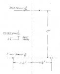
nola mike I measured my 4.3 mount locations with a tape measure. The pic below gives the horizontal dimensions. These are probably close enough for you to locate your front mounts. The vertical distance between front and rear mounts is a little iffy since I was standing on my head, and measuring each relative to the spark arrester/engine cover.

I'd drop your front mount surface 1/2" lower than this. You can add aluminum plate under the mounts if you run out of adjuster travel. Better to end up too low than too high.

Larson built the mount structure inward off the side of the stringers.

4.3 Mounting dimensions.JPG
 

nola mike

Vice Admiral
Joined
Apr 22, 2009
Messages
5,519
harringtondav , thanks for that. That's an overhead view, and the middle part you're saying is a side view of the front mount, 2.5" higher than the rear? I'm going to give myself plenty of fore/aft wiggle room for the mount structure, and I may shoot for 1/2" too low. If I need more than 1/2" adjustment, yeah, an aluminum plate is certainly not difficult. Although using Rick Stephens template should get me well within the ballpark. 1/2" over 17" is a ton of a fudge factor.
 

Rick Stephens

Admiral
Joined
Aug 13, 2013
Messages
6,118
Ya all tagged me and got me to subscribe to your post. That means I get to weigh in :^).

I would not go more than a little low. 1/8 or so at most. I went spot on from the Merc drawing.. I built the wooden layers first , stuck em in using just PB and found them a 1/2 inch too tall, so I dropped a skilsaw 1/2 inch down and made a bunch of parallel cuts in the tops then chiseled and sanded off to finish height minus 1/8" I then used 1708 for the long pieces (probably a waste) and plain ol heavy CS which lays down on weird shapes really well. I was using epoxy and not poly so I could get best adhesion. The plywood sandwich was just PB with 3/4 CDX. Don't see a lot of need for more strength of basically a foot of wood with a crap load of 1708 laid down along the stringers into the transom.

The factory spec is really clear off the drawings giving you rear mount to front mount centers, left to right side center width and how tall based on transom angle and rear mount height. I own a welding shop with some odd machining equipment. Following those is no different than what I do day to day. But I get it that it can make one uncomfortable if they don't do a lot of measuring, layout and fabbing. It will work! It will make sense and it will look right as it comes together. I am happy to help. So post your pics.

Rick
 

nola mike

Vice Admiral
Joined
Apr 22, 2009
Messages
5,519
Ha, I'm going to keep tagging Rick Stephens until this project is done. Once I get to the carb I won't let you sleep. Rear mount to front centers shouldn't be an issue, I'll make the mounts (what is the term for this? mount base i guess? The mounts are the part attached to the engine I think) plenty long. Center to center just need to worry about the oil pan, I'll be a little generous there as well. Someone posted that the squish mounts are different height from the solids, don't know if that's true. Also planning on plain ol exterior ply v. cdx, reading about potential moisture issues with the pressure treated. I'll I guess make it a game time decision about height, and see how confident I feel in my jig setup. I don't have a lot of tools (esp weird stuff) where I'm doing the work, and there's nothing nearby. If I make a mistake, I lose at least a day. 13' angle is a fairly precise measurement.
 

harringtondav

Commander
Joined
May 26, 2018
Messages
2,450
The factory spec is really clear off the drawings giving you rear mount to front mount center
Dang Rick, I searched high and low for an official Merc drawing/spec on the mounting dims before I uncovered my boat with my tape measure. ....how about a link to your source?

Nola Mike, the only add I have is there is room to move the front mount structure to center on the right side. At least 2". Left side is tighter due to the PS oil cooler. Mine is about 1" from the mount structure.

But wider is better when you drop a nut or drain plug into the bilge. :rolleyes:
 

Rick Stephens

Admiral
Joined
Aug 13, 2013
Messages
6,118
Dang Rick, I searched high and low for an official Merc drawing/spec on the mounting dims before I uncovered my boat with my tape measure. ....how about a link to your source?

Nola Mike, the only add I have is there is room to move the front mount structure to center on the right side. At least 2". Left side is tighter due to the PS oil cooler. Mine is about 1" from the mount structure.

But wider is better when you drop a nut or drain plug into the bilge. :rolleyes:

https://www.mercurymarine.com/en/us/documents/installation-drawings/
 

harringtondav

Commander
Joined
May 26, 2018
Messages
2,450
I had to pull my 4.3 to replace a frozen front mount, and to repair a twisted off lag on each side. Several methods for grubbing out the twisted off stumps. But I excavated the mount surface down 1/4" finished including a layer of glass. I fabed 1/4" aluminum plates so I could bridge over the stumps when I lagged the plates down. Then I tapped the plates for 3/8" SS machine screws to attach the mounts, and SS hanger bolts to lag the plates. Now if I have to pull the engine again I won't have to worry about twisted off lag bolts.

FYI When I bought the new mounts I had the choice of Merc mounts @ $85 each, or these at $35 ea. The Merc mounts are now aluminum castings. The $35 mounts are the same as my original cast iron mounts, with the same mfg markings as my original.

Search for BUSHINGS INC DF-216 ENGINE MOUNT, 3/4" ADJUSTABLE STUD

Click image for larger version  Name:	Larson stringer.jpg Views:	3 Size:	677.8 KB ID:	10854835
 

nola mike

Vice Admiral
Joined
Apr 22, 2009
Messages
5,519
From that drawing it looks like I might hit the water pump if the mount base extends too far to the front or middle on the starboard side? That's for the serp belt setup, but I think the v-belt should be the same?
 

Rick Stephens

Admiral
Joined
Aug 13, 2013
Messages
6,118
The only drawings are from 96 onwards. But, they are pretty good. I have v-belts on my '93 non-Vortec block. Nothing came even close to hitting stringers or front mount crossmember for the inlline 4 motor. I would think your bigger 370 crossmember is even further ahead, but don't know that.

If you need any comparison measurements, let me know. I can easily get approximate measurements from , most likely, crankshaft centerline for you.
 

nola mike

Vice Admiral
Joined
Apr 22, 2009
Messages
5,519
Got the supports fabbed up, going to thrown them in tomorrow hopefully. Used ply and 2x, and wood glued them together. So now I have a nice block to lay on the (uneven but sanded) bilge floor. Do I just want to glop PB on the floor and side of the stringers, or pre-wrap the blocks with glass, or coat with resin first, or put a layer of CSM between the transom floor and the wood block, or...
 
Status
Not open for further replies.
Top