Had boat in water first time today

Rick Stephens

Admiral
Joined
Aug 13, 2013
Messages
6,118
Have to resize the picture to under 2MB (which is quite large enough for a online photo).

Or use photobucket to post pictures. Here's the forum guise to posting pictures: Photo Upload Tutorial
 

Bradmxz

Seaman
Joined
Apr 18, 2016
Messages
59
No Title

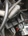
I cropped it quite a bit. Not sure if you'll be able to tell anything from this or not
 

Attachments

  • photo243365.jpg
    photo243365.jpg
    93.9 KB · Views: 1

Bradmxz

Seaman
Joined
Apr 18, 2016
Messages
59
Ok I'm trying to adjust the timing like you said but my problem is the 2 white wires on the distributor is actually one on mine. I can't install a jumper because it's already together. Does this mean it's in base timing mode all along. You can see in the pic that I uploaded the wire is a loop
 
Last edited:

Bradmxz

Seaman
Joined
Apr 18, 2016
Messages
59
Also check compression this morning all is good and can verify the tach isn't reliable. While giving the engine pumps of throttle it went from 1000 rpm up to 2000 rpm and while the engine came back down the tach never
 

Rick Stephens

Admiral
Joined
Aug 13, 2013
Messages
6,118
It appears you are correct. The shift interrupt connector, the one used while running the boat and that is connected to the shift interrupt switch, only has a single wire. The base timing connector, used to set initial timing, has the wire loop and is supposed to have the non-looped wire clipped to positive voltage source, looks like it is the one used in your picture. Without knowing how or what the black wire is attached to I don't know how your advance is working, but I don't think you can have a proper interrupt circuit as when the black wire is hooked to positive it will just drop your timing to base, not kill the engine. Whoever installed the distributor didn't know what they were doing.

Rick
 

alldodge

Moderator
Staff member
Joined
Mar 8, 2009
Messages
42,633
As before to set timing correctly we need the engine serial number.

1 BTDC for serial number 0L096999 and below
1 ATDC for serial number 0L097000 - 0L00340999
2 ATDC for serial number 0L341000 and above

Look above the starter for a ID plate

You either need the timing adapter delco p/n 10486133, or google delco est timing adapter. The plug installed will be removed during timing.
fetch


Very important - DO NOT connect the timing adapter power lead to 12V until after the motor is running. This is a spelled out in the document Rick posted.

This plug can also be made if you can find the standard 4 pin GM connector
fetch
 

Bradmxz

Seaman
Joined
Apr 18, 2016
Messages
59
I posted the serial number in another post. But I don't believe it's the cover belonging to the engine it has details for points gap on it and it's quite easy to see there are no points in my ignition
 

Rick Stephens

Admiral
Joined
Aug 13, 2013
Messages
6,118
You need to have the correct interrupt circuit wire installed, that gets unplugged and the one in your picture installed, with black attached to positive, to set your timing. Needs to be done right.

Screen Shot 2016-05-10 at 8.10.31 AM.png
 

Bradmxz

Seaman
Joined
Apr 18, 2016
Messages
59
Ok the way it's wired is the black wire is running to the shift interrupt switch. So can I right now assume it's in base timing mode? So basically the plug that is installed on my engine is a plug to allow base timing without jumping the wire?
 
Last edited:

Rick Stephens

Admiral
Joined
Aug 13, 2013
Messages
6,118
I am not sure how the advance works when the looped jumper is installed..... it is only in base timing when the black wire is connected to positive, which only happens on your boat when you shift out of gear under a load.


I do know it's not supposed to be hooked up that way.
 

Bradmxz

Seaman
Joined
Apr 18, 2016
Messages
59
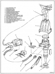
This is what I'm thinking if it's in base timing mode now I can set the timing and then just snip the white wire to allow the timing to advance when needed? According to the diagram you posted on the last page the single wire is supposed to go to the shift interrupt with a single wire in the plug. The plug installed on mine is the base timing plug so there's no need for a jumper? So I should be able to set my base timing and unhook the white wire which acts as the jumper and my ignition should be able to advance as normal. Ofcourse I'm just guessing here. That's the exact way the engine came to me so I don't know what the other guy had done with it. That could be half my problem. It's always in base timing mode and the ignition can't advance with I give throttle
 
Last edited:

Bradmxz

Seaman
Joined
Apr 18, 2016
Messages
59
I just want to say thanks very much for your guys help. I never would have realized anything out of whack with the wiring if you hadn't noticed it
 

Bradmxz

Seaman
Joined
Apr 18, 2016
Messages
59
Any thoughts? If I cut the white wire then it should be hooked up as normal right?
 

alldodge

Moderator
Staff member
Joined
Mar 8, 2009
Messages
42,633
STOP do not cut anything

The connector with the black wire on it goes to the shift interrupter as you mentioned. To get it in base timing, you remove the connector from the distributer.

Plug in the timing adapter (you need to buy one or make one) Start the motor and get it up to temp. Once up to temp (warm is ok) connect the bare wire coming from the timing adapter and connect to 12V battery power, not from the alternator. Once the 12V is connected while motor is running, then and only then will you be in base timing
 

Bradmxz

Seaman
Joined
Apr 18, 2016
Messages
59
The connector I have is exactly the same as the one you mentioned to make. So can't I just take the black wire off the shift interrupt switch and start the engine then connect the black wire to 12v on the battery. I then should be in base timing mode. Once base timing is set. I should be able to reinstall the black wire on the shift interrupt switch and snip the white wire cause it's only acting as the jumper. Then there will only be signal from the black wire regardless. Is this not logical
 

alldodge

Moderator
Staff member
Joined
Mar 8, 2009
Messages
42,633
Ok. Why can't I use the black wire as the 12v once the engine is running

According to the pic posted of the distributer, I didn't see the white wire until just now, kind of blended in for me, my bad. The wire staying connected would cause issues.

To get in base timing disconnect the black wire from the interrupter. Once running connect to 12V, disconnect and cut the white wire to put in normal. Base timing is applied when 12V is applied, the shift interrupter applies a ground to kill spark momentarily.
 

Bradmxz

Seaman
Joined
Apr 18, 2016
Messages
59
Ok thank you. That's what I was thinking. Maybe that could be some of my backfire problem. When throttle is applied the timing can't advance because the white wire is looped together.
 
Top