Installing new Tachometer 1990 Force 120 Outboard

capricuddy92

Cadet
Joined
Jun 21, 2017
Messages
29
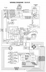
Just bought a Faria 32805 Euro 7000 rpm Tachometer for my 1990 force 120 hp outboard. The boat did not come with a tachometer, so I do not see any grey or purple wires under the dash. On the engine block there is a purple section to attach a lead wire. Is it as simple as connecting that electrical port to the tach, and then the 12v and ground wires to the back of the tach?

Please let me know.
 

legalfee

Petty Officer 1st Class
Joined
May 10, 2018
Messages
396
I have a 1995 90hp and the tach wire comes from the regulator rectifier and it's gray. You need to find a wiring diagram for your model.
 

Redbarron%%

Chief Petty Officer
Joined
Dec 7, 2017
Messages
479
Some of these engines have 20 pole alternators and and some 12 pole. Your tach is (possibly a 12 pole and will work.
For wiring either one of the yellow going to the rectifier / regulator or the gray wire from the Rectifier / regulator will work for input to the tach.
If the engine was set up for the tach it should have a gray wire that you can extend to the tach on the console or perhaps fins an unused wire already run to the panel.
Here is a link to the tach manual:
https://fariabeede.com/site_manuals/IS0012ac.pdf
On your 1990 outboard I would not be sure about the purple wire, but is is often a 12 volt from the switched 12 volt ignition switch.
In the manual it seems to say that the pre 1991 Force had the 20 pole alternator and no new tachs are being made.
It is possible that tis 2 " tach could be used:
https://fariabeede.com/site_manuals/IS0344_A_Tachometer-2in-Var-Freq.pdf
 

jerryjerry05

Supreme Mariner
Joined
May 7, 2008
Messages
18,084
Redbarron: The 1995 and the 1990 are WAY different.
The 95 used Mercury ignition, the 90 used Force/ Prestolite.
They won't match for that application.

The tach: is it a 20 pole?
Contact
www.
teleflexmarine
.com to see if they make them?

223115349203 e-bay has one that says it fits??


Depending on the year of the boat???
They made the purple wire standard on Force applications.
They taped it back at the end of the wiring harness.
Look under the dash and see if it's there?
Then it's a simple thing to add jumper wires for the power and ground.
 

capricuddy92

Cadet
Joined
Jun 21, 2017
Messages
29
Redbarron: The 1995 and the 1990 are WAY different.
The 95 used Mercury ignition, the 90 used Force/ Prestolite.
They won't match for that application.

The tach: is it a 20 pole?
Contact
www.
teleflexmarine
.com to see if they make them?

223115349203 e-bay has one that says it fits??


Depending on the year of the boat???
They made the purple wire standard on Force applications.
They taped it back at the end of the wiring harness.
Look under the dash and see if it's there?
Then it's a simple thing to add jumper wires for the power and ground.

Yes, I hve one that is adjustable that works with multiple poles up to 20. I have the wiring diagram for my engine, I just am not sure where to attach the signal wire.
 

Jiggz

Captain
Joined
Oct 23, 2009
Messages
3,909
Signal wire can either be a gray, purple or yellow (one of the AC lines off the stator) depending if the rectifier/regulator has been replaced or still the original. If you have the purple wire off the regulator/rectifier, I'm quite sure that is the tach signal wire. To be sure, check for continuity (resistance check) between the purple wire and one of the yellow wires. If there is continuity then it is the signal wire.
 

legalfee

Petty Officer 1st Class
Joined
May 10, 2018
Messages
396
Wiring diagram
 

Attachments

  • photo302336.jpg
    photo302336.jpg
    156.6 KB · Views: 20

Redbarron%%

Chief Petty Officer
Joined
Dec 7, 2017
Messages
479
If you have one that is adjustable most are made to use pulses from the alternator coils. If you have a gray wire coming from the rectifier (regulator) then use that one
If you have two wires that go to the rectifier from the coil then tap off one of those.
I don't know if your motor is 12 or 20 poles, but if you pick one then is the output nearly right?
If you have 20 poles and you use 12 then it will read quite a bit high and if opposite the it will read quite a bit low.
If I remember properly you have a + 12 volt and a negative or ground terminal and a signal connection (and maybe an internal light).
Ignition would be one thing, but I think these tachs work off the AC from the alternator and really do not connect to the ignition at all, bit I reserve the right to be wrong, standard disclaimers are hereby declared.
Again I cannot speak from experience but many outboards had a small square rectifier screwed on the electrical plate
610Lz-tkJFL._SX466_.jpg

CDI-152-9209_lg__49596.1469112966.500.750.jpg


and two wires from the alternator coil under and within the flywheel go to two terminals and + 12 DC from one and the last one goes to ground.


For the rectifier / regulator the yellow wires go to the alternator coil and the red wires are +12 the gray wire is for the tach.
Ground is through the metal enclosure.
If you have the square rectifier without the regulator you can get one from I boats or other sources good for up to 60 amps, not that your coil will supply near that much.
 

legalfee

Petty Officer 1st Class
Joined
May 10, 2018
Messages
396
This is the rectifier from CDI Electronics. If you looked at the wiring diagram you would see four connections. There are two and three wire versions though. The third wire goes to the middle connection if necessary.
 

Attachments

  • photo302339.jpg
    photo302339.jpg
    4.3 KB · Views: 0

Redbarron%%

Chief Petty Officer
Joined
Dec 7, 2017
Messages
479
The rectifier will have two connections for the alternator coils and one for the + 12 volt out and the fourth for ground or if three terminals the ground is made through the metal part of the rectifier internally.
Often the AC inputs are marked with ~ and the output +
 

jerryjerry05

Supreme Mariner
Joined
May 7, 2008
Messages
18,084
Depends on the year and make of the boat whether or not the harness has the lead for the tach.
If it was made from 84-93/4 it should have the purple lead in the harness.
That's if the wiring harness is Force ???

Tell me about the boat? Year, make?
 

capricuddy92

Cadet
Joined
Jun 21, 2017
Messages
29
It is a 21 foot 1990 bayliner capri cuddy with a 1990 Force 120 outboard.

I did connect the tach to the rectifier and it worked? I then saw it hooks up to a purple wire going to the controls. So I should just have to splice it and should be good!

However I am starting up at 2900 RPM so this is going to be fun adjusting now :)
 

Redbarron%%

Chief Petty Officer
Joined
Dec 7, 2017
Messages
479
Good luck, glad you found a wire to use.
What setting are you using?
Does the tach have a switch to select the pulses?
I guess that you can change the switch to get a reasonable reading
If you can borrow a strobe tach to set it that would be best.
To some extent with a boat set up with a good fit for the prop the tach is good for a relative reading to check performance ans select a repeatable cruise speed and being exact is nice, but not a big deal if it is off a little.
 
Last edited:

jerryjerry05

Supreme Mariner
Joined
May 7, 2008
Messages
18,084
2900 try turning the adjustment on the back of the tach.
They sell a tool: Tiny Tach under 20$
Very easy to use, hook up 1 ground and then wrap the other lead around the plug wire.
 

Redbarron%%

Chief Petty Officer
Joined
Dec 7, 2017
Messages
479
The Tiny Tach would be a good choice, but I have a question that I don't know the answer to.
That is that the flywheel has magnetic triggers that split and fire the trigger at TDC and at BDC (I know that the trigger coil moves, but the make up of the flywheel has splits 180* apart)
The question is does the ignition fire at TDC and BDC (relatively). This is known as wasted spark ignition since it does not actually fire the exhaust charge when it goes.
All that being said the Tiny Tach picks up the discharge pulse on the spark plug wire and therefore if MIGHT read twice as high as the engine is turning.
Anyone know for sure?
With the timing light you would not notice the extra flash on the black flywheel.
I have wondered about this after looking at the diagram of the 95 vs post 96 flywheel trigger magnets.
 

jerryjerry05

Supreme Mariner
Joined
May 7, 2008
Messages
18,084
No the tiny tach doesn't read like that.
When I installed it on different motors it read right, straight out of the box.
 

Redbarron%%

Chief Petty Officer
Joined
Dec 7, 2017
Messages
479
Thanks for the information on the tiny tach. Perhaps although the magnets have a break just like at TDC on the opposite side 180* at BDC. Perhaps the green and white and the white and green coils have an orientation that keeps them from firing at BDC side . There is a different orientation for the coils for 50 hp and below vs above.
I plan to get my 90 hp sport jet engine dressed before I install it and perhaps I can get a chance to hook up my scope to look for the output of the coils to see if it outputs through 360 degrees or not.
I will also try to take a look at the trigger output and perhaps use one to trigger the scope and check the frequency out put of the charging coil.
By the way I am converting the CDI system to a CDM with the moduled from a 200 hp late model engine and a ignition harness from a 3 cylinder 50 hp mercury.
 
Top