MCM 140 EST Ignition question/diagram

Leedanger

Petty Officer 1st Class
Joined
May 29, 2011
Messages
323
Gentlemen,

I have a MCM 140 #6156174 and it has an EST distributer/coil system on it. I'm not really familiar with these, I am hoping it's gonna make my life easier in the long run, but it looks like I have a little learning curve to conquer first.

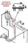
I'm having an issue getting the wiring harness all converted over (this engine is newer than the one I had in previously) and I also would like to know why the harness on the right side of this distributer is just cut and not hooked up. Refer to the picture but basically the harness on the right has 4 wires grn/grn-blck, blue/blue-blck...none of which are hooked up.

I guess what I need is a diagram for this type of ignition system and maybe some additional information of how and why it works. I'm sure I just need to do some reading if I can find the right sourse and I'll be good to go. Manual #4 which is what I have for this motor doesn't contain anything on this est system.

thanks!View attachment 116016View attachment 116017View attachment 116018
 

Don S

Honorary Moderator Emeritus
Joined
Aug 31, 2004
Messages
62,321
Re: MCM 140 EST Ignition question/diagram

I also would like to know why the harness on the right side of this distributer is just cut and not hooked up. Refer to the picture but basically the harness on the right has 4 wires grn/grn-blck, blue/blue-blck...none of which are hooked up.

Hate to be the one to tell you, but it's the wires on the LEFT side of your pictures that are cut, not the right. Took a bit before I realized the picture was reversed. What's up with that ???????
Looks like the wires are part of a non marine wiring harness, as those color codes are not marine.

You will only need 3 of those 4 wires to hook up to your shift interrupt system. See distributor and module picture below.

Here is some 3.0L information you will need, I will have to find another drawing of which 3 of the 4 you will need.
 

Attachments

  • 3.0 EST timing.pdf
    164 KB · Views: 0
  • EST dist.jpg
    EST dist.jpg
    79.9 KB · Views: 0

Leedanger

Petty Officer 1st Class
Joined
May 29, 2011
Messages
323
Re: MCM 140 EST Ignition question/diagram

Hhmmm....sorry about that, it is backwards....dunno. Regardless, in real life it is on the right, bow side of the motor. Appreciate the info, I will read through it all and then report back once I am more capable of helping you help me.

Cheers.
 

Leedanger

Petty Officer 1st Class
Joined
May 29, 2011
Messages
323
Re: MCM 140 EST Ignition question/diagram

Ok...now that I have had a chance to read the est test instructions perhaps someone could check to see if what I learned is correct. At the coil I should have on the left side harness the (+) which on mine is grey and the (C) which on mine is tan. Grey is my "batt" and tan is my "rpm", correct so far? On the right harness I just have the "pink" and "brown" which come from the left side harness on the distributer. The way it is currently wired, which from what I can tell is incorrect, tan is also being run up to the shift interrupter switch, to tell you the truth I have no idea where the tan at the switch is coming from, that's just what I deduced.

The color coding is indeed different on the right side of distributer harness:
--- = Green
B = Green/WH
R = Blue
E = Blue/WH

Using my colors listed, if I am correct what I need to to is disconnect the tan from at the switch and replace it with the Green/White (B) and then bullet connect Blue/Wh (E) & Blue (R) together....? Or do I need to keep the tan @ the shift interrupter and ad the Grn/Wh (B) to it? I do know that when the key is on (not running just in "ON" position at ign, I have 12.8V at that tan wire on the shift interrupter switch.

So to be more succinct with my question, what I do with the (E) and (R) from the right side harness on the distributer and what's the deal with the tan wire I have going to the shift switch. On a points system normally the Brwn would go to the (-) on the coil and that would be my rpm and tan would be my (+).
Does (+) still = (+) and does (C) = (-) on the est coil?

Thanks for the help, I hope my description is comprehendible, let me know if it's not and I will just make a video.

View attachment 116237
 

Don S

Honorary Moderator Emeritus
Joined
Aug 31, 2004
Messages
62,321
Re: MCM 140 EST Ignition question/diagram

Ohhhh,, (sigh) you have the old style wiring. Let me look a bit, but the tan doesn't sound right.
On your dash, do you have an ammeter? and do you have a 90A fuse on the starter with a red wire on it?
 

Don S

Honorary Moderator Emeritus
Joined
Aug 31, 2004
Messages
62,321

Attachments

  • 140 wiring.pdf
    353.9 KB · Views: 0

Leedanger

Petty Officer 1st Class
Joined
May 29, 2011
Messages
323
Re: MCM 140 EST Ignition question/diagram

Ohhhh,, (sigh) you have the old style wiring. Let me look a bit, but the tan doesn't sound right.
On your dash, do you have an ammeter? and do you have a 90A fuse on the starter with a red wire on it?

No, it's the 40A Breaker up by the thermostate. I haven't had a chance to run this motor in the water yet to see if I can get it out of reverse, but it is running and it comes out of rev easy on trailer, but we'll see once there is some pressure on the prop. I suppose if I'm mindful of it, I could always just kill the motor and restart from neutral, but obviously I'd rather have it wired right the first time.

Attached is the closest diagram to how it's wired, I matched the rest of the dash to it, I just haven't corrected that part of the harness concerning the shift interrupter. Also, I have the switch grounded on one side and on the other it's the tan (which really is tan with a very light white stripe it looks like at second look) The diagram I attached says the green/wh as we already know and a purple coming up from the alternator should be connected....I don't understand why it would have the purple vs the ground, should I wire it this way?

The diagram you attached is exactly what I am used to wiring, that schematic is familiar to me, but this is the newer version in comparison. I am quite certain manual 13 has all the right info, even though the serial doesn't add to it.
 
Top