Re: MFG Gypsy 15 Tri-Hull Restore advice needed
Ok, finally got the opportunity to get some pics done for you guys. So here goes...
I already explained how I worked with the plywood sheets I can't say enough about making templates out of cardboard. Don't think that one template for the same part will work. It doesn't. I learned the hard way. Luckily I was able to correct the problem I encountered (2nd Stringer) without wasting any lumber. You need to make a template for EACH part. Even after using the templates you may need to do a little tweaking of the final pieces but the templates make life a lot easier. I was partially able to use the rear bulkhead template for the center one. The center one needed a little more heighth than the rear one but the bottom countour is the same as the back. The front bulkhead needed a completely separate template. The hull angle is different there.
In cutting the transom, you also have to keep in mind that there is an angle between the transom and the floor to take into consideration as well as the sides of the transom where it flares out. I used an angle guage to measure the angles and set my jigsaw when I was ready to cut the areas that needed an angle.
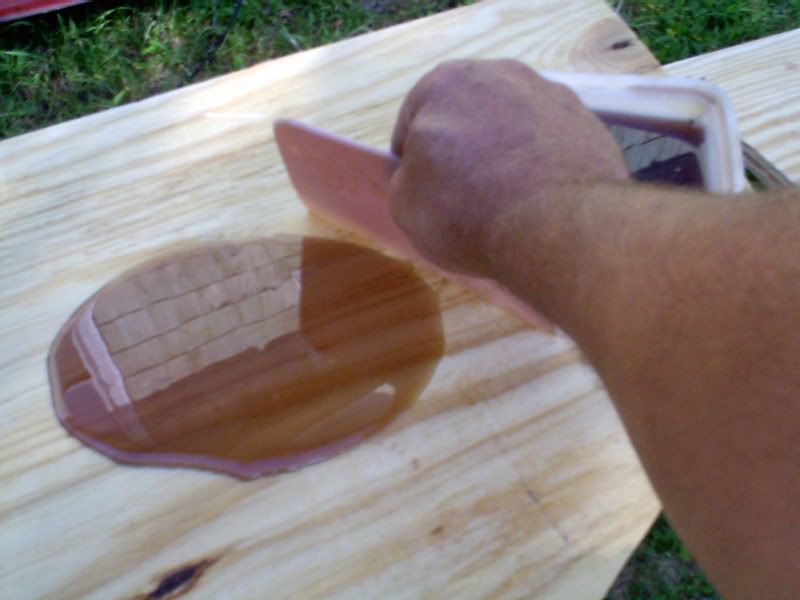
I used a jigsaw for all of my cuts with a long fast cut Dewalt Blade. Believe me there's nothing fast about it when you're cutting through an inch and a half of plywood! Because I beefed up the corners of the transom skin and floor, I used a router to put a 1/2" radius around the back-side edges of the transom so it would clear the additional glass there.
Now here's a bit of a tip for you. Everything doesn't have to fit like a glove. Close is good enough. That's what PL Premium, peanut butter, and glass is for. You can make everthing nice and tight later. Concentrate on getting a close fit. It doesn't have to be perfect. In fact as you get to making the templates you'll find that nothing about the boat's construction was perfect when the boat was 1st manufactured!
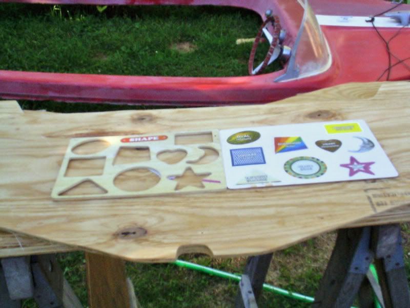
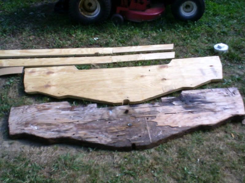
Here's a shot of the templates and the finished parts...
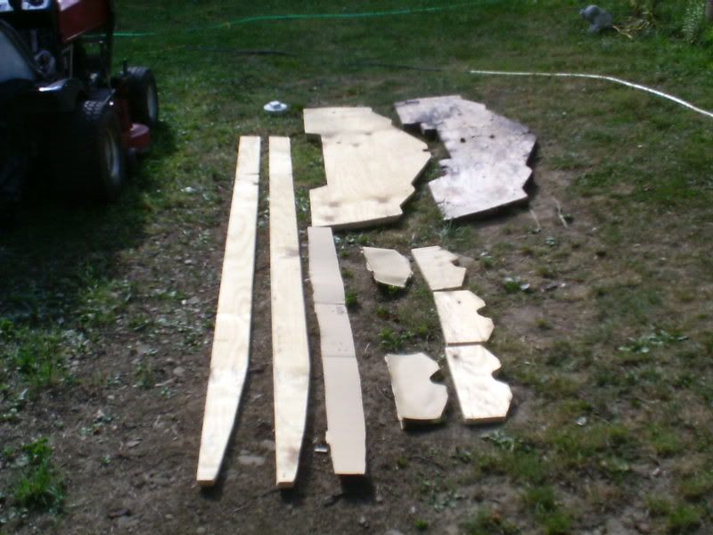
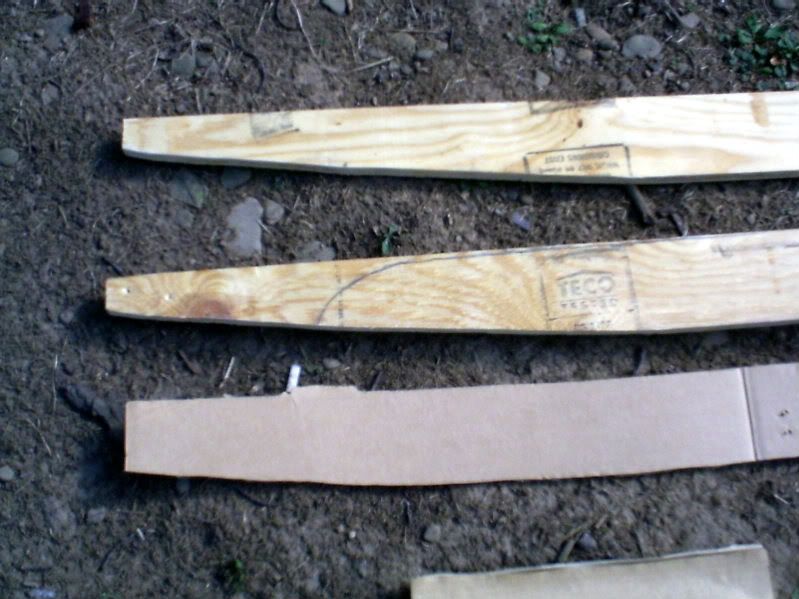
In an earlier post I showed how I copied the hull contour for the stringers. The template pictured only deals with that contour. Not the stringer height. The stringers in this boat are 4" tall until the contour starts and remain level on top. Knowing that, I made the template long enough to get back to the part of the hull that was straight. I cut 2 strips of ply 4 inches wide and then lined up the template with the bottom and front of the stringer and then drew my cut lines. I should have made a second template for the 2nd stringer. I didn't and ended up regretting it to an extent. I was able to fix the problem.
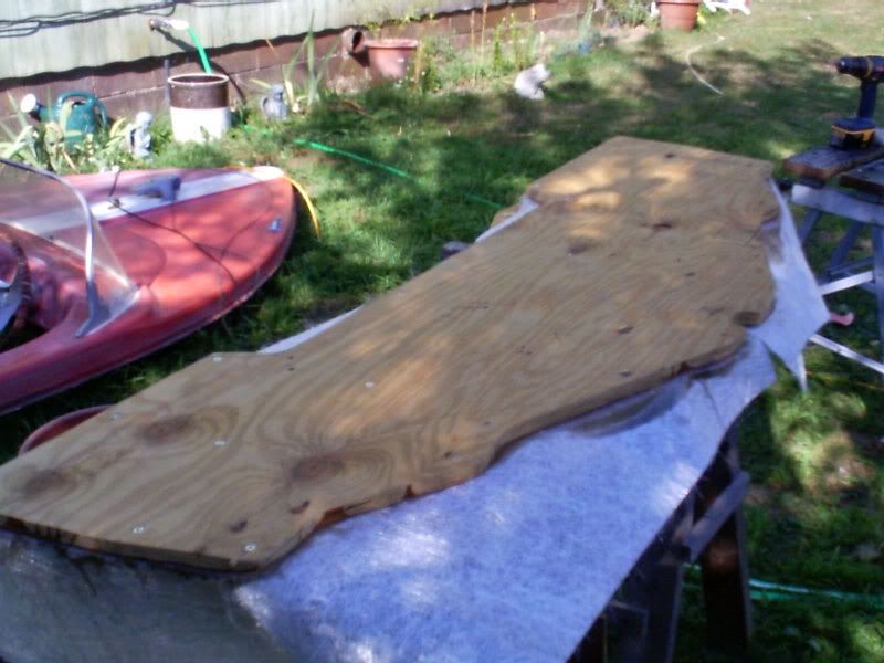
This pic shows the end result of the Transom using the old one as a template. The old one looks larger due to the picture angle. You'll also notice in this pic that the ends of the stringers shown are angled to fit the angle of the Transom. This is something MGF DIDN'T DO! Currently the Transom is held together with drywall screws so that nothing moves. When I'm getting ready to laminate the transom halves together I'll put in a couple of 1/4" dowels to re-align the transom halves and then remove the screws.
The end result...
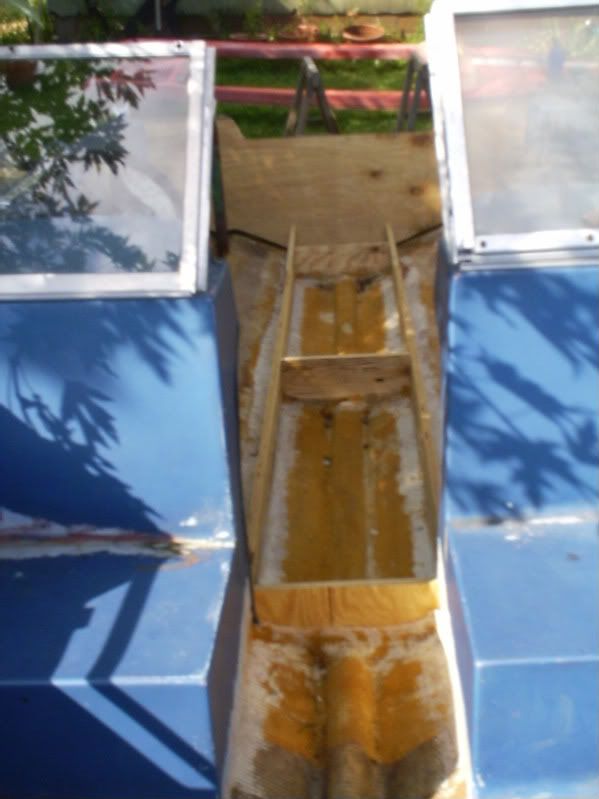
From the bow to the stern...
The Transom...
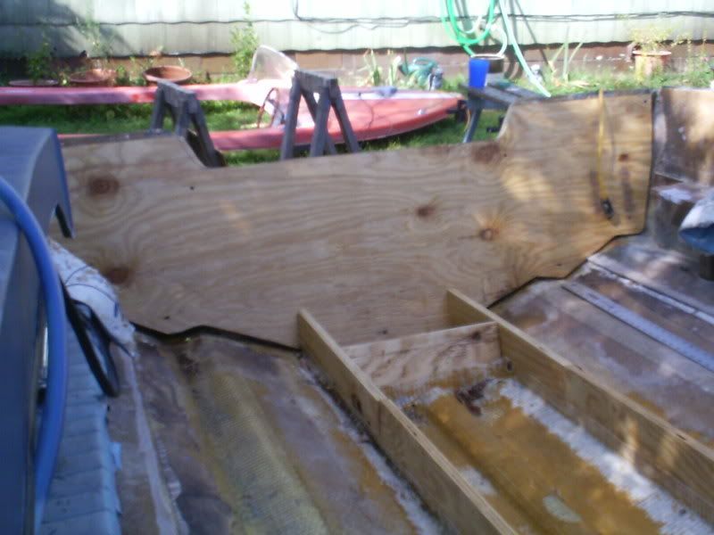
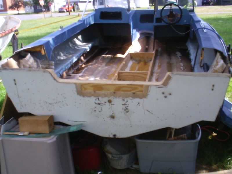
From the back. Notice the area that's going to be glassed back in where someone cut the transom down before to accomodate a short-shaft motor.
There you have it. Next on the agenda, laminating the transom halves.
Ok, finally got the opportunity to get some pics done for you guys. So here goes...
I already explained how I worked with the plywood sheets I can't say enough about making templates out of cardboard. Don't think that one template for the same part will work. It doesn't. I learned the hard way. Luckily I was able to correct the problem I encountered (2nd Stringer) without wasting any lumber. You need to make a template for EACH part. Even after using the templates you may need to do a little tweaking of the final pieces but the templates make life a lot easier. I was partially able to use the rear bulkhead template for the center one. The center one needed a little more heighth than the rear one but the bottom countour is the same as the back. The front bulkhead needed a completely separate template. The hull angle is different there.
In cutting the transom, you also have to keep in mind that there is an angle between the transom and the floor to take into consideration as well as the sides of the transom where it flares out. I used an angle guage to measure the angles and set my jigsaw when I was ready to cut the areas that needed an angle.
I used a jigsaw for all of my cuts with a long fast cut Dewalt Blade. Believe me there's nothing fast about it when you're cutting through an inch and a half of plywood! Because I beefed up the corners of the transom skin and floor, I used a router to put a 1/2" radius around the back-side edges of the transom so it would clear the additional glass there.
Now here's a bit of a tip for you. Everything doesn't have to fit like a glove. Close is good enough. That's what PL Premium, peanut butter, and glass is for. You can make everthing nice and tight later. Concentrate on getting a close fit. It doesn't have to be perfect. In fact as you get to making the templates you'll find that nothing about the boat's construction was perfect when the boat was 1st manufactured!
Here's a shot of the templates and the finished parts...
In an earlier post I showed how I copied the hull contour for the stringers. The template pictured only deals with that contour. Not the stringer height. The stringers in this boat are 4" tall until the contour starts and remain level on top. Knowing that, I made the template long enough to get back to the part of the hull that was straight. I cut 2 strips of ply 4 inches wide and then lined up the template with the bottom and front of the stringer and then drew my cut lines. I should have made a second template for the 2nd stringer. I didn't and ended up regretting it to an extent. I was able to fix the problem.
This pic shows the end result of the Transom using the old one as a template. The old one looks larger due to the picture angle. You'll also notice in this pic that the ends of the stringers shown are angled to fit the angle of the Transom. This is something MGF DIDN'T DO! Currently the Transom is held together with drywall screws so that nothing moves. When I'm getting ready to laminate the transom halves together I'll put in a couple of 1/4" dowels to re-align the transom halves and then remove the screws.
The end result...
From the bow to the stern...
The Transom...
From the back. Notice the area that's going to be glassed back in where someone cut the transom down before to accomodate a short-shaft motor.
There you have it. Next on the agenda, laminating the transom halves.