achris
More fish than mountain goat
- Joined
- May 19, 2004
- Messages
- 27,468
:facepalm:
I've just seen the price on those pumps. You know what they charge for them here (-32, 116)? Over $600! Yep, 10 times your price...
Chris.........


yes, motor mounts were a pain. you should round those edges and corners really good.
Vortec heads have non adjustable valvetrain unless you convert them
The 11-15 lb-ft is correct for the intake
So I think that's a typo in the mercruiser manual. Rereading it it appears that 35 was for the old heads, but the instructions specifically say gen+ and earlier get the same torque unless I'm misreading.

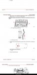
achris , here's what I'm looking at in #18 and 25
")
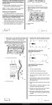
achris , I think I'm in the right manual (s). That screenshot has the '99 date and the diagram is the 8 bolt manifold.
Same with #18, which covered both. I have the same page you posted with those torque specs at the beginning of the chapter in both manuals. At any rate I'll do the correct torque, hope it doesn't leak. Going to have to wait till Monday. This weekend I'll reglass that one mount, install the transom shield bolts and gimbal bearing, and maybe see if I can free that shift cable with a ½ socket pounded on. Otherwise I'll just replace the core.