Simple, easy to make DVA adapter for standard Multimeter

Status
Not open for further replies.

achris

More fish than mountain goat
Joined
May 19, 2004
Messages
27,468
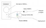
Finally done... Here's the circuit to make a simple, but usable DVA adapter...

Now testing outboard engine ignition systems will be easier... You can build it then wrap it in 'silly tape, or encapsulate it in epoxy, or make a little box for it... Your choice. Just make sure you use the exact components I used... Components shouldn't cost more than about $6... Available at any electronics shop...


attachment.php
 

Attachments

  • DVA adapter.jpg
    DVA adapter.jpg
    36.3 KB · Views: 122
Last edited:

achris

More fish than mountain goat
Joined
May 19, 2004
Messages
27,468
Re: Simple, easy to make DVA adapter for standard Multimeter

Here is another design for one Iboats..... funny thing cap and resistor are different.
http://forums.iboats.com/showthread.php?t=371144&highlight=dva+adapter

Didn't see that one as I don't do white engines....

This is a design I did quite a few years ago, just had to redo the math for the values. I also used a Greencap (not an electrolytic), as an electrolytic is polarity sensitive and if the test leads are put on backwards, it will explode.

Chris.......
 

Texasmark

Supreme Mariner
Joined
Dec 20, 2005
Messages
14,794
Re: Simple, easy to make DVA adapter for standard Multimeter

Values look good. I got to scrounging around the parts bin last week when this subject was popular and found a pair if 3612's, a .47 600v and a 3.3M resistor. Haven't built it up but should work. If not, I see that I can double the R and have a working unit.

On the electrolytic, your diode protects it from accidental lead reversal, but it has to be installed with the diode as shown and the + of the cap on the cathode of the diode to keep it from doing what you said. Course you could tie 2 electrolytics in series wiring - to - and it wouldn't matter if you were concerned about accidental polarity reversal. We used to do that when we couldn't find a non-polarized electrolytic in the value we wanted for some bipolar signals we wanted to filter and there was no diode involved.

Mark
 
Last edited:

achris

More fish than mountain goat
Joined
May 19, 2004
Messages
27,468
Re: Simple, easy to make DVA adapter for standard Multimeter

Values look good. I got to scrounging around the parts bin last week when this subject was popular and found a pair if 3612's, a .47 600v and a 3.3M resistor. Haven't built it up but should work. If not, I see that I can double the R and have a working unit.

Your peak value will bleed off at twice the rate. No biggy, just have to look at the meter quicker ;)

On the electrolytic, your diode protects it from accidental lead reversal,

True.... :rolleyes:

but it has to be installed with the diode as shown and the + of the cap on the cathode of the diode to keep it from doing what you said. Course you could tie 2 electrolytics in series wiring - to - and it wouldn't matter if you were concerned about accidental polarity reversal. We used to do that when we couldn't find a non-polarized electrolytic in the value we wanted for some bipolar signals we wanted to filter and there was no diode involved.

Mark

Good trick....

It's been (quite a few) years since I played with designing.... Those brain cells must be a bit rusty (or is that Alzheimer kicking in???)

Chris.......
 

j_martin

Admiral
Joined
Sep 22, 2006
Messages
7,474
Re: Simple, easy to make DVA adapter for standard Multimeter

Values look good to me. If the meter's jumpy, the capacitor is too small. If it bites you after you disconnect, the resistor is too high a value.

Some meters might have a low enough input resistance that the resistor is totally unneeded.

This is called, in electronic parlance, and integrator circuit. The idea is to allow current to flow into the capacitor only when the input voltage is higher than the capacitor voltage, and to hold that voltage for a period of time determined by the values of the capacitor and the resistor.

First time I saw one was in high school electronics in the early 60's. It's used to create the blanking bias so the diagonal trace lines don't show up on a b&w TV during the vertical retrace. When the cap's bad, you get the lines.

I must be getting old. I can repair a vacuum tube car radio from memory.

John
 

Nickledimed

Petty Officer 3rd Class
Joined
Feb 16, 2009
Messages
87
Re: Simple, easy to make DVA adapter for standard Multimeter

Sorry to grag this old topic up, but I was thinking about building this.
Once I do, how do I use it?
Please forgive my ignorance...
 

achris

More fish than mountain goat
Joined
May 19, 2004
Messages
27,468
Re: Simple, easy to make DVA adapter for standard Multimeter

Sorry to grag this old topic up, but I was thinking about building this.
Once I do, how do I use it?
Please forgive my ignorance...

Exactly the same as you would to measure voltage. All the DVA does is turn the multimeter into a peak voltage meter. Normally a multimeter reads average voltage, not peak. On an outboard the average is very low, so we need to see the peak voltage, hence this adapter.

Tells us your problem and we can give you instructions on finding it...

Chris......
 

Nickledimed

Petty Officer 3rd Class
Joined
Feb 16, 2009
Messages
87
Re: Simple, easy to make DVA adapter for standard Multimeter

Im looking for a way to test the switch box on a 1974 65hp Merc.
 

achris

More fish than mountain goat
Joined
May 19, 2004
Messages
27,468
Re: Simple, easy to make DVA adapter for standard Multimeter

Im looking for a way to test the switch box on a 1974 65hp Merc.

Post a new question in the Merc Forum and you'll get lots of answers (just ignore the ones that tell you that it can be tested with a multimeter on resistance). Also post up whether the engine has a distributor or not. best is to post the serial number of the engine....

Chris........
 

SuperNova

Lieutenant
Joined
Mar 16, 2007
Messages
1,455
Re: Simple, easy to make DVA adapter for standard Multimeter

I have a question in regards to this whole DVA thing. I understand the need and the use of a DVA adapter, the question is....Why won't a "peak hold" type DVM work. I'm figuring an oscilloscope would work fine, but not many people have one. I just don't understand why a DVM that can freeze peak readings wouldn't work. Thanks in advance for your time.
--
Stan.
 

achris

More fish than mountain goat
Joined
May 19, 2004
Messages
27,468
Re: Simple, easy to make DVA adapter for standard Multimeter

I have a question in regards to this whole DVA thing. I understand the need and the use of a DVA adapter, the question is....Why won't a "peak hold" type DVM work. I'm figuring an oscilloscope would work fine, but not many people have one. I just don't understand why a DVM that can freeze peak readings wouldn't work. Thanks in advance for your time.
--
Stan.

A peak hold meter would work... As long as the meter is capable of holding the peak of a non-sinusoidal wave....

Chris....
 

SuperNova

Lieutenant
Joined
Mar 16, 2007
Messages
1,455
Re: Simple, easy to make DVA adapter for standard Multimeter

A peak hold meter would work... As long as the meter is capable of holding the peak of a non-sinusoidal wave....

Chris....
Well, I know we can use them to catch square waves, but I am not sure about the other patterns of non-sinusoidal waves. What pattern are we looking for? Or do I have to hook up my o-scope?
 

achris

More fish than mountain goat
Joined
May 19, 2004
Messages
27,468
Re: Simple, easy to make DVA adapter for standard Multimeter

For the trigger the duty cycle is VERY low, like about 5%. The stator is a triangular wave, and the coil pulse from the switchbox is VERY short.

Chris........
 

SuperNova

Lieutenant
Joined
Mar 16, 2007
Messages
1,455
Re: Simple, easy to make DVA adapter for standard Multimeter

Alright, thanks for the info...you've been very helpful and informative. I think just for giggles I will hook up a scope and check out the patterns...sounds like it could be an interesting exercise. Thanks again!
 

achris

More fish than mountain goat
Joined
May 19, 2004
Messages
27,468
Re: Simple, easy to make DVA adapter for standard Multimeter

Alright, thanks for the info...you've been very helpful and informative. I think just for giggles I will hook up a scope and check out the patterns...sounds like it could be an interesting exercise. Thanks again!

If you can post up the waveforms I'd love to see them. Do you have a standalone CRO or a PC/USB one? I recently bought a 40MHz USB oscilloscope. Haven't used it in anger yet, but it looks pretty good with the cal waveform...

Chris..........
 

j_martin

Admiral
Joined
Sep 22, 2006
Messages
7,474
Re: Simple, easy to make DVA adapter for standard Multimeter

I've looked at the trigger leads with an O-scope. Interesting thing is that the firing of a plug puts an artifact on the waveform so it's real easy to see the timing. The basic waveform is sinusoidal distorted by the non linear termination at the ends. Plug fires about half way up the waveform, modified by the bias voltage, so if you drag the bias down toward ground, it'll fire lower on the waveform. (earlier)

The circuit we're playing with is called an integrator. It will store nearly the peak voltage of any waveform with a frequency substantially above the decay rate of the R-C network.
 

achris

More fish than mountain goat
Joined
May 19, 2004
Messages
27,468
Re: Simple, easy to make DVA adapter for standard Multimeter

I've looked at the trigger leads with an O-scope. Interesting thing is that the firing of a plug puts an artifact on the waveform so it's real easy to see the timing.

I'm guessing 20,000+volts up your clacker would put an artefact on your waveform too... :D

j_martin said:
The basic waveform is sinusoidal distorted by the non linear termination at the ends. Plug fires about half way up the waveform, modified by the bias voltage, so if you drag the bias down toward ground, it'll fire lower on the waveform. (earlier).

That makes sense. The bias sets the level for the circuitry to fire the capacitor.

j_martin said:
The circuit we're playing with is called an integrator.

Sorry John, I really don't like big words, so I call it a DVA circuit. :D

j_martin said:
It will store nearly the peak voltage of any waveform with a frequency substantially above the decay rate of the R-C network.

Thought I just said that... :confused::confused:

Thanks for the input John.... Always nice to have the backing of someone who actually knows what they're talking about.....

Chris...........
 

SuperNova

Lieutenant
Joined
Mar 16, 2007
Messages
1,455
Re: Simple, easy to make DVA adapter for standard Multimeter

If you can post up the waveforms I'd love to see them. Do you have a standalone CRO or a PC/USB one? I recently bought a 40MHz USB oscilloscope. Haven't used it in anger yet, but it looks pretty good with the cal waveform...

Chris..........
It's a 2-channel standalone, so I can compare patterns on circuits that interact or are timed to each other. I use it to help diagnose some automobile circuits. It works on analog waves and digital waves as well as secondary ignition circuits, ABS sensors (A/C generators), hall-effect sensor circuits and it is really great for spotting TPS sweep flaws. Just never tried hooking it up to an outboard before, so I'm curious. Just for the record, I'm just an Auto tech who has to diag basic 12 volt circuits for the most part, not an electrical engineer or PC board techie or anything like that.
 
Status
Not open for further replies.
Top