Temp Sensor Vacuum Sensor wiring 84 crossflow 100hp

edfishing2

Petty Officer 2nd Class
Joined
Mar 6, 2011
Messages
144
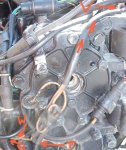
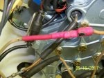
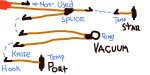
The vacuum switch has one lead that goes to ground. The other lead goes to an insulated lug on the bracket. The wiring has twin tan (labeled V) wires with a ring terminal that goes to this insulated lug. The wiring diagram shows one tan wire on the boat side wiring harness and 3 tan wires on motor side wiring harness. One tan wire is very clear it hooks to one of the thermal sensors in the head on the starboard side (not shown in photo). The diagram shows a low oil sensor but I do not know of a low oil sensor in my outboard. If you look at the photo it looks like one of the thermal sensors was not even hooked up (marked with a T). The diagram shows the port thermal sensor in-series with this vacuum switch.

Here is the question. Where does this in-series happen as it looks like there are two of the blade type connectors. Has someone (previous mechanic/owner) hooked up the low oil sensor to one leg of the vacuum incorrectly or the thermal switch wire ? Pin out of motor side red connector may help me out.
Evinrude E100WTLCRS
 

Attachments

  • Tan Wires.jpg
    Tan Wires.jpg
    122.1 KB · Views: 0

Big flop

Petty Officer 1st Class
Joined
Apr 6, 2011
Messages
290
Re: Temp Sensor Vacuum Sensor wiring 84 crossflow 100hp

All the tan wires end up at the same place.
The warning horn.
If the port temp switch is unhooked it should
be hooked up. Does the temp switch look like
it's been hot? A little melted?
Low oil tan wire is for VRO (oil injection) oil tank.
 

edfishing2

Petty Officer 2nd Class
Joined
Mar 6, 2011
Messages
144
Re: Temp Sensor Vacuum Sensor wiring 84 crossflow 100hp

I unwrapped all of the wiring harness and one tan wire has a red section perhaps a diode. Both temp switches have been tested and work fine. I was just confused about not having a knife connection to put it . The twin wires that go up to the vacuum switch are hooked up to the two knife connectors. but there is not another knife connection available.

The temp switches look ok to me. I swear I would never recommend someone to remove the head covers. That was a pain. Skip this step in the omc manual for powerhead removal. VRO was not available in 84 I think but if it was it is not on my outboard.
 

edfishing2

Petty Officer 2nd Class
Joined
Mar 6, 2011
Messages
144
Re: Temp Sensor Vacuum Sensor wiring 84 crossflow 100hp

Here are more photos showing inside of wiring harness and vacuum switch and lost temp switch knife connector and red something that has been shorted at one point in time. And yes it is the same block as photo in original post. Kinda a before and after saga.
 

Attachments

  • 000_0043.jpg
    000_0043.jpg
    60.2 KB · Views: 0
  • 000_0044.jpg
    000_0044.jpg
    138.8 KB · Views: 0
  • 000_0045.jpg
    000_0045.jpg
    144.1 KB · Views: 0
  • 000_0046.jpg
    000_0046.jpg
    143.1 KB · Views: 0

Big flop

Petty Officer 1st Class
Joined
Apr 6, 2011
Messages
290
Re: Temp Sensor Vacuum Sensor wiring 84 crossflow 100hp

I think your port temp switch wire got removed
during someones creative repair. Since theres a problem
at the red heat shrink, I think I would open that up and add
the needed temp switch wire during repair?
 

edfishing2

Petty Officer 2nd Class
Joined
Mar 6, 2011
Messages
144
Re: Temp Sensor Vacuum Sensor wiring 84 crossflow 100hp

The red heat shrink was wrapped up inside the wiring harness and wanted to make sure it was or was not original equipment. I will cut into the cover and see if diode or just connectors are inside. Can someone tell me if the tan wire for all threes sensors (2 temp and one vacuum) is hot or just completes a ground for the horn? The first photo in the last group of photos shows a splice that look original. This tan wire goes (after splice) on to the starboard temp sensor. Before the splice one leg goes to red heat shrink (I cut inside red heat shrink and there was the missing two hook connectors).

Ok so coming out of the big red connector there one short tan wire with hook/knife connection. And the other tan wire it long and goes to Y splice. One end of splice continues to starboard temp sensor. The other end of splice goes to another hook/knife connector.

The vacuum wire has long twin tan wire with ring terminal at one end and it goes to insulated junction at vacuum switch with other wire from vacumm switch. So I have to connect Port knife/hook temp switch to and hook/knife connector from twin wire vacuum wire to same hook?

Is all of this supposed to be in series? ie one big loop from one of tan wires at big red to the other tan wire at big red plug?

Does anyone need more photos?
 

Big flop

Petty Officer 1st Class
Joined
Apr 6, 2011
Messages
290
Re: Temp Sensor Vacuum Sensor wiring 84 crossflow 100hp

All brown wires are are hooked together
(one big loop).
They send a ground to the warning horn,
if the motor overheats or there's a fuel
restriction.
You can turn the key on (motor not running)
and ground one of the brown wires on the
block and the horn should beep.
No diode needed till 1989 and newer for
quick-start and slow
 

edfishing2

Petty Officer 2nd Class
Joined
Mar 6, 2011
Messages
144
Re: Temp Sensor Vacuum Sensor wiring 84 crossflow 100hp

Not trying to beat a dead horse (well not too badly) but attached is what I think I should do. I don't think the wire complete a circuit(not a loop) until the switches actuate. So I think the wiring diagram in the book showing one tan wire for low oil sensor is correct and should not be used.

I guess if the unused knife goes to same place then it wouldn't matter.
 

Attachments

  • temp.jpg
    temp.jpg
    53.7 KB · Views: 0

edfishing2

Petty Officer 2nd Class
Joined
Mar 6, 2011
Messages
144
Re: Temp Sensor Vacuum Sensor wiring 84 crossflow 100hp

Put ohm meter on knife connector I planned to ignore and it connects to all of the others electrically. If it was used it would have been short.
 

Big flop

Petty Officer 1st Class
Joined
Apr 6, 2011
Messages
290
Re: Temp Sensor Vacuum Sensor wiring 84 crossflow 100hp

The connector you plan to ignore is hooked
to the other brown wires and that is the way
it should be. All brown wires hook together
then lead to the horn through the one
Brown wire in the boat harness.
Hope that makes sense?
 

Big flop

Petty Officer 1st Class
Joined
Apr 6, 2011
Messages
290
Re: Temp Sensor Vacuum Sensor wiring 84 crossflow 100hp

If your ohms testing brown wires to
ground looking for shorts the brown
wire should be unhooked from the
horn first or it may show falt thru
the horn.
 

edfishing2

Petty Officer 2nd Class
Joined
Mar 6, 2011
Messages
144
Re: Temp Sensor Vacuum Sensor wiring 84 crossflow 100hp

Thanks for the reply. Powerhead is in middle (last stages I hope) of rebuild and setting on workbench. I was hooking up all the wires and noticed that one of the temp sensors was not hooked up previously and using the one available would have been to short to reach. I was just testing from red plug to each of the two tan wires to confirm they are the same and they are indeed the same. No connection to ground until switches are made. It was confusing to see two tan wires at the red connection and when I unwrapped the harness I see one is split again.
 
Top