Trim pump wiring help

GSPLures

Chief Petty Officer
Joined
Sep 3, 2019
Messages
564
How are you all doing, when it comes to wiring the trim pump up I am ignorant (in this case ignorance is NOT bliss😵).

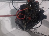
I am going to explain the issues as thoroughly as I can so I apologize for the long post. I am working on a mercruiser 140 with a mc-1 outdrive

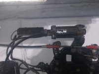
I believe I have a Frankenstein setup from the previous owner. I know the bellhousing assembly has been changed to a different style it has the junk yard yellow paint pen on it saying it was for a 165, I also believe it was for a newer setup. From what I have read my bellhousing should of had the nails holding it together but this one has the bolts under the trim limit switches that require the special tool to take apart.

When I bought the boat the drive was off and there were some cut wires and some not hooked up. I do not believe the trim wires were hooked up (it was a while ago, I gutted the boat and rebuilt).

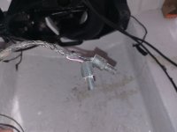
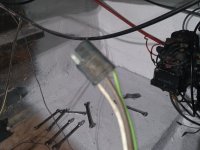
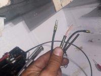
There are the 4 wires coming through the transom assembly which 2 are cut and the others have the male bullet connections.

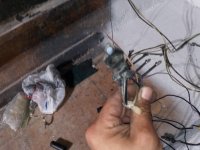
There are 2 wires coming from the trim sender on the top of the inner transom plate. Which also have the male bullet connections.

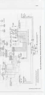
I have looked at all the schematics in the mercruiser manual and I do not see anything about the gimbal mounted sensors although a parts blowout on mercruiserparts shows parts numbers for a gimbal with and without the senders.

Which wires do I hook up and where?

Not sure if some of the wires are not used which is why they were cut or what is going on

I appreciate your help
 

Attachments

  • 20210623_160022_compress69.jpg
    20210623_160022_compress69.jpg
    822.7 KB · Views: 14
  • 20210623_160027_compress9.jpg
    20210623_160027_compress9.jpg
    762.6 KB · Views: 13
  • 20210623_160038_compress15.jpg
    20210623_160038_compress15.jpg
    881.6 KB · Views: 11
  • 20210623_154305_compress94.jpg
    20210623_154305_compress94.jpg
    714.9 KB · Views: 14
  • 20210623_154335_compress14.jpg
    20210623_154335_compress14.jpg
    835 KB · Views: 15

GSPLures

Chief Petty Officer
Joined
Sep 3, 2019
Messages
564
After sleeping on it and doing a little more research I may have a solution

I am assuming(I know the saying) that I should hook up the trim sender the way the manual shows and leave the wires coming from the switch unhooked. Looking at the wire and hydraulic schematics it should work

Does this seem like a reasonable assumption?

Thank you.
 

Attachments

  • Screenshot_20210624-051419.png
    Screenshot_20210624-051419.png
    626.5 KB · Views: 9

ccoon520

Seaman
Joined
Apr 25, 2021
Messages
67
After sleeping on it and doing a little more research I may have a solution

I am assuming(I know the saying) that I should hook up the trim sender the way the manual shows and leave the wires coming from the switch unhooked. Looking at the wire and hydraulic schematics it should work

Does this seem like a reasonable assumption?

Thank you.
I just ran into this on my 76 sea ray. So as far as the sender goes one wire goes to the helm (on mine it was a purple wire with a whit stripe) and connects to the trim gauge. The other one goes to ground.

The switch will have 2 wires that both go to connectors on the trim pump harness. Direction does not mater. I will post pictures of what mine looks like once I get home.
 

GSPLures

Chief Petty Officer
Joined
Sep 3, 2019
Messages
564
I just ran into this on my 76 sea ray. So as far as the sender goes one wire goes to the helm (on mine it was a purple wire with a whit stripe) and connects to the trim gauge. The other one goes to ground.

The switch will have 2 wires that both go to connectors on the trim pump harness. Direction does not mater. I will post pictures of what mine looks like once I get home.
I appreciate it.

So I would just leave the gimbal mounted sensors unhooked and use the wires coming from the trim sender.

Sorry Im just a bit confused by my setup because. I have the newer gimbal mounted senders and the older style transom plate sender and it was all unhooked when I bought the boat.
 

ccoon520

Seaman
Joined
Apr 25, 2021
Messages
67
I appreciate it.

So I would just leave the gimbal mounted sensors unhooked and use the wires coming from the trim sender.

Sorry Im just a bit confused by my setup because. I have the newer gimbal mounted senders and the older style transom plate sender and it was all unhooked when I bought the boat.
My sender and switch mount onto the bell housing.

They are these pucks: https://www.amazon.com/Mercruiser-S...silver+MC-1+trim+switch&qid=1624556818&sr=8-1

They use the hinge pins that the bell housing rotates around (the 2 threaded things with the proprietary pattern that needs that special adapter) to locate the trim position. The sender goes on the Starboard side and the switch goes on the port side. The sender is just an indicator and only connects to the gauge. The switch limits the travel of the outdrive so once properly adjusted you can't lift it higher than recommended without using the override function. Here is a link to a thread that I had when I was first chasing this stuff down. It has some wiring diagrams from achris and some pictures:


In Picture 20210425_182116 on the left side of the trim pump there are 2 loose connectors, one that is connected to the purple wire and one that is connected to a blue and a black wire. This is where the trim switch plugs go. In the other picture there is a purple wire with a white stripe that terminates in a yellow butt connector (this was something left by the PO). This is where one of the trim sender wires goes. The other one goes to a ground (mine is currently grounded on the alternator because that was unfortunately the best option).

I will post pictures of how the pucks mount on the bell/gimbal housing when I get home but hopefully this helps a little bit.
 

GSPLures

Chief Petty Officer
Joined
Sep 3, 2019
Messages
564
My sender and switch mount onto the bell housing.

They are these pucks: https://www.amazon.com/Mercruiser-S...silver+MC-1+trim+switch&qid=1624556818&sr=8-1

They use the hinge pins that the bell housing rotates around (the 2 threaded things with the proprietary pattern that needs that special adapter) to locate the trim position. The sender goes on the Starboard side and the switch goes on the port side. The sender is just an indicator and only connects to the gauge. The switch limits the travel of the outdrive so once properly adjusted you can't lift it higher than recommended without using the override function. Here is a link to a thread that I had when I was first chasing this stuff down. It has some wiring diagrams from achris and some pictures:


In Picture 20210425_182116 on the left side of the trim pump there are 2 loose connectors, one that is connected to the purple wire and one that is connected to a blue and a black wire. This is where the trim switch plugs go. In the other picture there is a purple wire with a white stripe that terminates in a yellow butt connector (this was something left by the PO). This is where one of the trim sender wires goes. The other one goes to a ground (mine is currently grounded on the alternator because that was unfortunately the best option).

I will post pictures of how the pucks mount on the bell/gimbal housing when I get home but hopefully this helps a little bit.
I have the pucks on the bellhousing, I also have the older style trim sender on the transom plate. The bellhousing was swapped out to a newer part that wasnt the original part for the boat.

Thats where my confusion is coming from. I am not sure if I should use the senders on the bellhousing or the sender on the transom plate.

The hydraulic lines go to the sender on the transom plate so not sure how or if I can even wire up the senders on the bellhousing.

The pump I have is the original single solenoid pump

Again I appreciate your help
 

GSPLures

Chief Petty Officer
Joined
Sep 3, 2019
Messages
564
So I started going through miles of wire that has been hacked into multiple times by people who shouldnt own a wrench let alone do electrical on a boat (sorry for the rant😁).

The pump is a presolite if that helps. One line from the bellhousing runs into the bottom of the pump and the other into the trim sender on the top of the transom plate.

I will try to explain the wiring as short as possible.

From the switch on the dash it has a purple,red,green, and blue wire.

The harness to the back of the boat has a brown, green, and white wire going to a plug.

The opposite side of the plug:
-White wire to stern light
-brown wire 3 way spliced to blower and appears to be a ground.
-the ground is spliced to a black wire with a female bullet connector(assuming for the black wire coming off of the trim sender)

A purple/white wire is running from the transom to under the dash with a female bullet connector(assuming this is for the purple/white wire from the trim sender)

Since the bellhousing senders (hockey pucks) coming through the transom have 4 connections (2 of them have been cut so only 2 bullet connectors) are those connected to the harness which seems it would bypass the trim sender on the top of the transom plate? (Dont know if that would work since the hydraulic line is ran to the trim sender on the transom plate)

Or

Leave those wires from the bellhousing senders unconnected and connect the bullet connections from the trim sender on the top of the transom plate?

Once I have this figured out i will make proper splices in the wiring!

I hope this posts makes sense it makes my head spin so i can only imagine if you cannot see and touch it.
 

Attachments

  • 20210624_164421_compress78.jpg
    20210624_164421_compress78.jpg
    1.2 MB · Views: 6
  • 20210624_164628_compress51.jpg
    20210624_164628_compress51.jpg
    800.8 KB · Views: 5
  • 20210624_165051_compress90.jpg
    20210624_165051_compress90.jpg
    890.5 KB · Views: 6
  • 20210624_165420_compress39.jpg
    20210624_165420_compress39.jpg
    878.9 KB · Views: 5

GSPLures

Chief Petty Officer
Joined
Sep 3, 2019
Messages
564
I did some testing on my trim pump.

I press the buttons and get nothing. The connections back there look bad so I am going to clean and replace.

I jumped power through the solenoid and got a click and then continuity. So that seems ok.

-i jumped 12v to the terminal that connects the blue wire i get a click and nothing

-jumped 12v to the green wire and get nothing.

But nothing happens.

-I disconnected the pump motor blue and green and ground.

-I jumped 12v to the green and ground to the blue I get a click and then nothing from the motor

-I jump the opposite way and get the same thing.

I would like to avoid just replacing the whole thing if I can but not sure where to start.

To me the solenoid seems to check out and the motor seems bad, am I correct?
 
Joined
Mar 27, 2010
Messages
3,008
Green and blue are both power/hot wires. green is for grass/down, blue is for sky/up. That's how I remember them. There should be a separate black ground wire for the motor.
 

GSPLures

Chief Petty Officer
Joined
Sep 3, 2019
Messages
564
Green and blue are both power/hot wires. green is for grass/down, blue is for sky/up. That's how I remember them. There should be a separate black ground wire for the motor.
Yes, I grounded the black wire and jumped 12v to each wire and nothing happened.

I took the motor off and it was real dirty so I cleaned everything with 00 sand paper and electrical contact cleaner. I ran through the tests in the manual with my multimeter and all checked out after cleaning so i am going to put it back on in a little bit and see if I can get the motor to run.
 

GSPLures

Chief Petty Officer
Joined
Sep 3, 2019
Messages
564
Just put the motor back on and it spins so cleaning it worked. Tomorrow I will put the solenoid back on and test the system again
 

GSPLures

Chief Petty Officer
Joined
Sep 3, 2019
Messages
564
Got everything hooked back up and it works so it was just the motor really needed a proper clean up.

Thank you all for the replies and happy 4th
 
Top