Beginner Here

Spooner2010

Petty Officer 3rd Class
Joined
Dec 1, 2010
Messages
96
I have done the search and have found many answers to many of my questions. HOWEVER. :D

Quick skinny? 16? aluminum fishing boat. Anything electrical was cut and stripped by previous owner. No switches left, no breakers, no nothing. Just ignition wire and starter cables. So pretty much clean slate. I can wire it how I want (basically how you guys tell me). In other words I could end up wiring it wrong. That?s why I?m here.

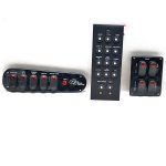
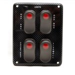
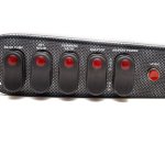
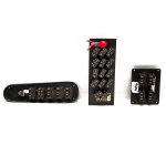
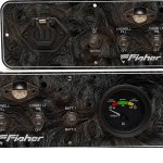
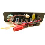
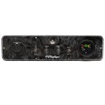
I bought 3 switch panels and 1 breaker panel. See pix.
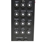
Breaker Panel.jpgAll Switch Panels Front.jpgLights Switch Panel.jpgMain Switch Panel.jpgAll Switch Panels Back.jpg

Among the hundred questions I have one that jumps out at me and I have not been able to find in searches is this. In my research I have found that all wires must start with a positive connection and end with a negative connection. The ?loop?. Where I become puzzled is if I have a breaker panel with 14 breakers, then that would equal 14 wires coming IN on one side of the panel and 14 wires coming OUT of the other side of the panel. Does that mean that 14 wires will connect to the positive battery post and 14 wires will connect to the negative post? Common sense would say this is not the case so how do you change one wire off the battery into 14 wires going into the breaker panel?

Next question is this. The switches on two of the panels have a red light on the switch to indicate that it is on. On the back of these switches there are 3 prongs. I?m guessing one is to luminate the little red light when it?s on. So how does that get wired? Pig tail off the downstream side?

I have several other questions but I leave you guys to chew on this one for tonight.

Thanks in advance guys.
 

Fireman431

Rear Admiral
Joined
Sep 17, 2007
Messages
4,292
Re: Beginner Here

When wiring switches, if the switch is a simple on/off, then it is 12v+ going to one leg of the switch and 12v+ coming from the other leg to the accessory. If the switch has a built in light, the third prong is for a 12v- wire to illuminate the lamp. This third prong will either be marked or will be apart from the other 2 prongs. Same concept with the breakers (although no lamp). Power feed to one side of the breaker and the other side goes to the accessory (light/pump/etc). DO NOT connect 14 wires to the negative post. If you do, all 14 breakers will trip immediately when you flip them on.

When powering the breaker panel, the basic idea is to run a 0 or 1-2 gauge wire to a bus panel (depending on the design of the breaker panel). From the bus panel, each breaker will be wired with the appropriate sized wired feeding each circuit (usually 10-14 gauge). From there, each wire will go to the accessory it feeds. Each light/pump/etc should have a separate ground wire run to a ground bus bar which is fed from a single wire from the 12v- side of the battery.

Hope this helps.
 

Silvertip

Supreme Mariner
Joined
Sep 22, 2003
Messages
28,771
Re: Beginner Here

You have a 16 foot aluminum fishing boat! What on earth made you think you needed 14 circuit breakers. I doubt you can name 14 electrical devices on the boat. Here is a very basic wiring diagram and it applies to nearly every electrical device on the planet. If you did actually have 14 such devices, they would all be wired the same (except for Navigation lights).

Basicwiring.jpg


here is what the Nav/Anchor switch wiring needs to be!

NavSwitchWiring.jpg


Or this way:

Nav-AnchorSwitch.jpg


And if you really have no clue about how things should be wired, try the Generic wiring diagram in the "sticky" at the very top of this page.

Lastly, what values are each of the breakers on this 14 breaker panel. Are ANY of them rated less than 10 amps??

Almost forgot -- here is how an illuminated switch gets wired.

LightedSwitchWiring.jpg


And lastly again -- here is how current flows through "the loop". Follow the arrows.

LightingCircuit.jpg
 

Spooner2010

Petty Officer 3rd Class
Joined
Dec 1, 2010
Messages
96
Re: Beginner Here

DO NOT connect 14 wires to the negative post. If you do, all 14 breakers will trip immediately when you flip them on.

I figured as much. That's why I asked.

When powering the breaker panel, the basic idea is to run a 0 or 1-2 gauge wire to a bus panel (depending on the design of the breaker panel).

These size wires seem big to me. I'll only be feeding small pumps, lights, fish finder and maybe a stereo. Would that really draw enough juice to warrant a 0 gauge wire? I mean I don't even think my starter cables for my outboard are that big. I'm just asking. I follow you on the 10 to 14 gauge for each individual circuit. Also... If I?m understanding you correctly I?ll need a 14 gang bus on the positive side of the battery and a 14 gang bus on the negative side of the battery. Is this correct? Also are there any Bus Bars you would recommend over other bus bars? And? Is there a difference between a bus bar and a ground bus bar?

Hope this helps.

More than you know. Thank you.

You have a 16 foot aluminum fishing boat! What on earth made you think you needed 14 circuit breakers. I doubt you can name 14 electrical devices on the boat.

To be perfectly honest I found these really cool switches online that I just HAD to have. The breaker panel came with the switches. I don?t even know if I need it.

But I have a breaker for:
1.) Lights
2.) Bilge
3.) Horn
4.) Courtesy lights
5.) Aerator
6.) 12v Outlet
7.) Rod Box Light
8.) Fwd Recirc
9.) Aft Recirc
10.) L\W Lights
11.) Stereo
12.) Fish Finder
13.) Acc one
14.) Acc two

I don?t know if I?ll use them all but they are there if I ever need them. Or should I scrap it and get a fuse box instead? What would you recommend? I want to do this right the first time.

If you did actually have 14 such devices, they would all be wired the same (except for Navigation lights).

Just for kicks and giggles I got my son?s electrical science kit out of his toy box and tried to replicate the Nav/Anchor wiring diagram according to a 6 pronged switch. I could only get one light to illuminate at a time. I couldn?t get both to illuminate in one position and one to illuminate in the other position. What might I be doing wrong?

If you really have no clue about how things should be wired, try the Generic wiring diagram in the "sticky" at the very top of this page.

The ?sticky? is where I started. It was helpful but not near as helpful as these diagrams you have included in your post. If those would have been included in the sticky it would have answered a BUNCH of questions right off the bat. Is it alright or possible if I post them in the ?Generic Boat Wiring Diagram? thread? Or should we create another sticky?

Lastly, what values are each of the breakers on this 14 breaker panel. Are ANY of them rated less than 10 amps??

I looked but I didn?t find anything that stated their rating. They all look the same so I would guess that whatever the rating is ,all 14 of them are the same. Can you tell by their intended use how heavy of a breaker you would need? Would all these that I listed above fall within the ?less than 10 amps? category?


Thanks a ton Fireman and Silvertip. Your input has been a huge help.
 

pootnic

Chief Petty Officer
Joined
Aug 11, 2007
Messages
447
Re: Beginner Here

I'll try to answer acouple of your questions.
On the "sons electrical question".
Are you sure the switch is the same.I think where the 12V comes onto the switch maybe yours isn't connected to both poles,you need it at both sides so the jumper will work.
For your last question.
Your 12V outlet may be alittle over 10amp some are rated alittle higher(15amp) and maybe your stereo if you have an amp.
That first diagram should work for you with a breaker panel.
Only thing I might add is the circuit breaker in the diagram 1,is for the total amp draw of the fuses(breakers)panel.Then your fuseing(breaker) each device seperately after that,with the proper size fuse(breaker).The basic lighting circuit diagram(last 1) may show you better.
The wire size going to your bus(s) from battery,will depend on what your total amp draw(all the devices) is or will be in the future.
 

Fireman431

Rear Admiral
Joined
Sep 17, 2007
Messages
4,292
Re: Beginner Here

Let's say you were going to actually install a 14 circuit breaker panel in a 16' boat (I missed the size of the boat in the initial thread), the wire feeding the breaker panel has to be of sufficient size to carry the entire load in the even that ALL breakers are operating at the same time. This means all lights, pumps, radios, GPS, fishfinder, amps, etc have the potential to be operating at once. Will it happen? Probably not. Could it? Yes. The size of wire needed will depend on the total amp draw from all of your accessories, plus an additional 10-15%, and the length of run from the battery. If you are wiring only lights, small pumps, and a stereo, then forget about trying to put in a panel. The next owner may think it's wired for max use and load it up, resulting in it's own version of Chernobyl.

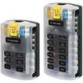
The only difference between a bus and a ground bus would be the ability to place fuses on the 12v+ side. As long as the run is short enough and all of your connections are good, you could run a #4 ground wire to a 6 terminal ground bus and have more than 1 accessory on each terminal. once all connections are made and secure, I usually spray a light coat of bettery terminal protectant spray on the ground bus screws. You would be surprised at the amount of corrosion that can occur in a short time and the games it will play with your electronic equipment.

fused bus.jpg
This is an example of a fused bus for 12v+

ground bus.jpg
This is an example of a 12v- bus

Silvertip's post (#4) shows a comibation bus in the top photo.
 

Spooner2010

Petty Officer 3rd Class
Joined
Dec 1, 2010
Messages
96
Re: Beginner Here

The size of wire needed will depend on the total amp draw from all of your accessories, plus an additional 10-15%, and the length of run from the battery.

I follow you. That makes perfect sense.


So let me ask you this. If I want a ?master? switch do I just run 0 gauge through the switch to the breaker panel/fuse block? Would the switch be before the 50 amp fuse or after?
 

Fireman431

Rear Admiral
Joined
Sep 17, 2007
Messages
4,292
Re: Beginner Here

Your biggest cable (0 gauge) would go to the starter from the battery. The next size (depending on the length of run/amps drawn) would go from the battery to the battery switch, with the 50 amp fuse of fusible link in line there. After the battery switch, the feed would go to the breaker panel/bus bar. This way, shutting off the battery switch would disconnect all power to the panel.

NOTE: Your bilge pump(s) should be wired with in-line fuses directly to a constant hot source, and preferably thru a switch that would allow you to turn it on manually if needed. An automatic float should also be wired as well, so it activates if incoming water gets too high. There should be no way to D/C the power from a float switch aside from removing the battery. If you need it, I'll post the wiring diagram for that.
 

Spooner2010

Petty Officer 3rd Class
Joined
Dec 1, 2010
Messages
96
Re: Beginner Here

NOTE: Your bilge pump(s) should be wired with in-line fuses directly to a constant hot source, and preferably thru a switch that would allow you to turn it on manually if needed. An automatic float should also be wired as well, so it activates if incoming water gets too high. There should be no way to D/C the power from a float switch aside from removing the battery. If you need it, I'll post the wiring diagram for that.

I?m not ready to wire for a Bilge Pump just yet Fireman 431, but I plan on putting one in in the near future. So it would great if you could post the wiring diagram for that. That way I can refer to this thread when I?m ready to install it.
 
Top