BEP Panel Switch Help

Captaingregw

Cadet
Joined
Oct 11, 2010
Messages
19
Good day All

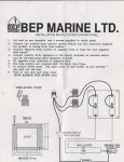
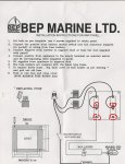
I decided I would install a BEP 900 4WP - panel switch in my boat.

Currently I have all the psotives on a Positive Stud and all the Negatives on a negative stud. under the dash

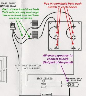
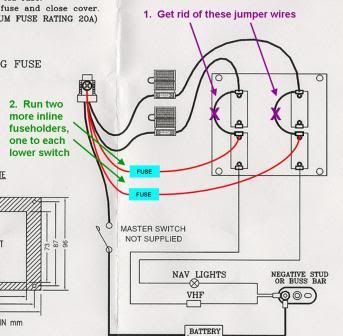
I see on the back of the switch only two wires with a inline 20A fuse on each.And they are joined to each panel on the back- But How do I connect the GPS, Stereo and VHF on these?

But the Switch is for 4 items- how do I connect all four items. This is what came with teh switch but I do not understand it.??

Please help
 

Attachments

  • scan0004.jpg
    scan0004.jpg
    145.4 KB · Views: 0

fish_on_the_deck

Petty Officer 3rd Class
Joined
Jun 30, 2010
Messages
94
Re: BEP Panel Switch Help

from the diagram it looks like the two wires with inline fuses are two positive feeder lines. I guess those fuses protect two switches each?? This panel does not have lighted switches, so there shouldnt be any negative wires going to the panel. Like STEP 4 on the instructions says, there should be terminals at the bottom of all four switches where you would attach the switch legs to go out to your loads. They may be 1/4" spade's or maybe #10 rings or something. Youll likely have to buy those connectors and build your cabling to your loads (crimp them).

Please dont take offense, but I really think those are some of the worst looking panels you can get. Thier only advantage is that they are dirt cheap... those labels will fall off before long, and putting two circuits on one fuse is just a poor design IMO.

Look at into THIS PANEL if you havent already bought yours... much nicer look (IMO) you can get it with or without breakers (I suggest with), it's a hand assembled panel for a resonobly (albeit more than the BEP panel) price and is fully wired and ready to install and you can customize professional looking switches and arrangements.

OK, I guess you did say you decided on BEP... so yeah... two positive input wires and you'll need to get some kind of connectors to tap into the switchable side. remember with this panel if one circut blows a fuse, then it will take another circuit down with it... makes troubleshooting a little harder.
 

Captaingregw

Cadet
Joined
Oct 11, 2010
Messages
19
Re: BEP Panel Switch Help

Thanks but I still don't get it, I don't see anywhere to connect into!

I assume the lower one is for the Negatitive, but with all the top ones taken . How do I connect?
 

fish_on_the_deck

Petty Officer 3rd Class
Joined
Jun 30, 2010
Messages
94
Re: BEP Panel Switch Help

Thanks but I still don't get it, I don't see anywhere to connect into!

I assume the lower one is for the Negatitive, but with all the top ones taken . How do I connect?

NO NEGATIVE... unless the panel has lights on it (ie. a little indicator light comes on when the switch is on) there shouldnt be any negative to the panel. Obviously the loads (sterio, VHF, etc) will have negatives, but they will not go to the switch panel, they should find there way straight back to the nagetive terminal on the battery somehow... no fuses... no switches on the negatives.

For the hook-ups for your loads... each switch should have an empty terminal... like the instructions step 4 says. I cercled where they should be on the attached pic. You will need to tap onto this terminal with whatever the mate is.

It would help if you have a question like: "I assume the lower one is for the Negatitive" try using paint to mark up your diagram, or a picture of the actual product... b/c im not exactly sure what "the lower one" is.

these switches are simple... one wire comes in that is always hot. One wire somes out that is only hot when the switch is on. Youve found the wires coming in (wires with inline fuse)... look on the body of the switch for the terminal where a whire should be coming out. you can use a voltmeter or a 12Vdc light bulb to test.

let us know if you found the terminals yet... or post a pic of the back of hte panel and I'll circle them for you.
 

Attachments

  • wiring pic.jpg
    wiring pic.jpg
    144.3 KB · Views: 0

ajgraz

Lieutenant Commander
Joined
Mar 1, 2010
Messages
1,858
Re: BEP Panel Switch Help

I'll take a stab at helping out, too:

BEP.jpg
 

Captaingregw

Cadet
Joined
Oct 11, 2010
Messages
19
Re: BEP Panel Switch Help

Thanks that makes sense! I was confused because the Diagram was saying the lower ones were to the negatitive buss bar.

Can I have another in line fuse for the Hot wire from the bottom 2. That way they are all protected with fuses?
 

ajgraz

Lieutenant Commander
Joined
Mar 1, 2010
Messages
1,858
Re: BEP Panel Switch Help

Can I have another in line fuse for the Hot wire from the bottom 2. That way they are all protected with fuses?

Yes, but you want those inline fuses to come before the switches, and to have one fuse for each individual switch. And you want to get rid of the jumper wires linking each pair of switches.

Illustrated, here's what you want to do:
BEP2.jpg
 

fish_on_the_deck

Petty Officer 3rd Class
Joined
Jun 30, 2010
Messages
94
Re: BEP Panel Switch Help

Yes, but you want those inline fuses to come before the switches, and to have one fuse for each individual switch. And you want to get rid of the jumper wires linking each pair of switches.

I agree! This is what I would do for a cheap, but improved solution. Also a separate little fuse block could be used, but this is easier/cheaper.

This way, if one fuse is blown you will only loose power to the "problem" circuit instead of the problem circuit AND its upstairs/downstairs neighbor.

nice diagram ajgraz... that should help out.
 
Top