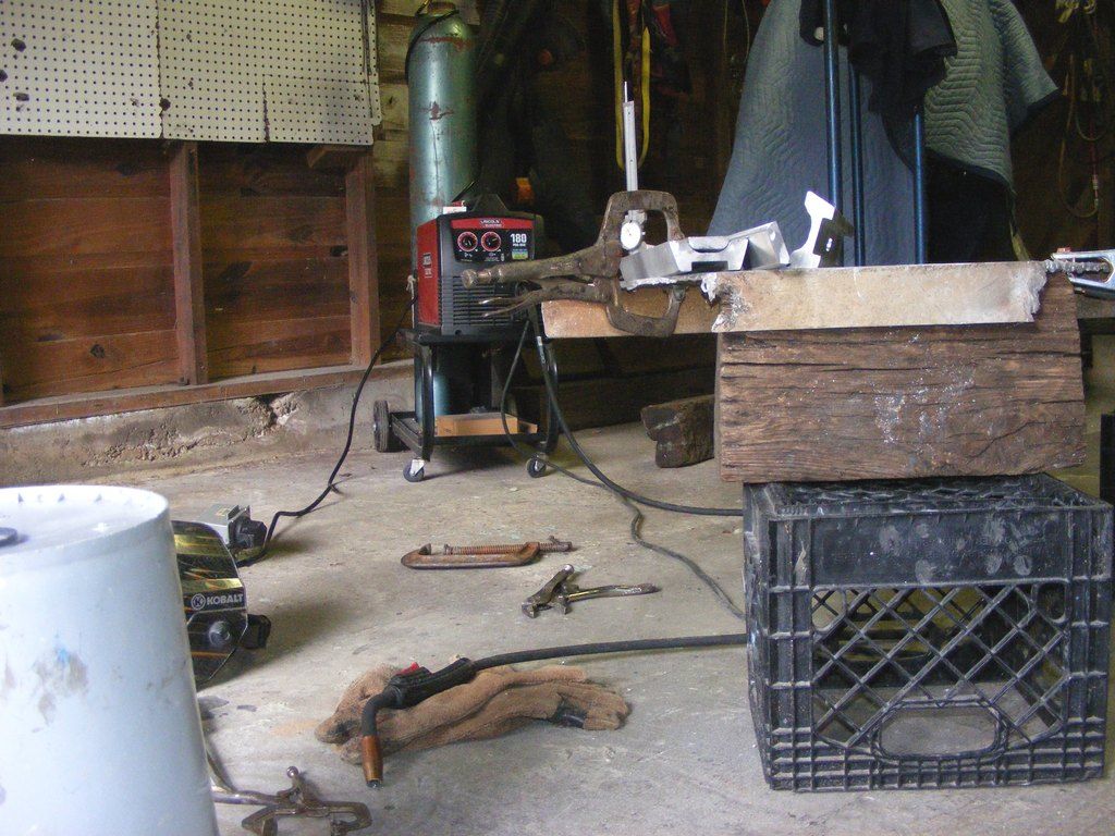
can of worms?

jrttoday

Lieutenant Junior Grade
Joined
Feb 8, 2010
Messages
1,081
wish me luck!!! This isn't stacking up to be easy, but am feeling confident about it working out. Confident about cussin, fussin, and getting a bigger hammer too LOL.
1st of all, putting the bolts in will have to be done as, or before she goes together. Lots of trial and error to see what has to go when? I'll let ya know just in case someone else is kwazy enough to try!!

http://

It's just sitting in there for now - except for two bolts top of the brackets, finger tight, and not even SS. Figure out in the morning where and how much to trim back on the brackets; they won't be directly load bearing like they would on for standard use. BUT!!! they will be subjected to some force??? and WILL have the standard 4 bolts holding them on.


Took the flat bar bracing, top and bottom, off - (8) 1/2x1" SS bolts and 8 roll pins total. Back and forth, WD40..... broke two bolts anyway. Not going to use heat against the boat; ground them off flush because I'm not going back with 'em. Maybe on top cos I have room on the forward side, but to t/t and brackets "should" tie it all in.

Back of the CMC will be scabbed over with landings for trim rods; not certain as to exactly how to do that yet? Possibly salvage yard has some? or I'll make something.... as usual LOL
 

jrttoday

Lieutenant Junior Grade
Joined
Feb 8, 2010
Messages
1,081
shaking his head while voicing extreme disapproval says "why?"
Because "I" do not have $12,000 for a new trim and tilt. But I do have a 1970 with only 10ish hours (as far as I can tell) on it and runs as good as anything out there; besides etc etc etc lol, I need something constructive to do.

http://

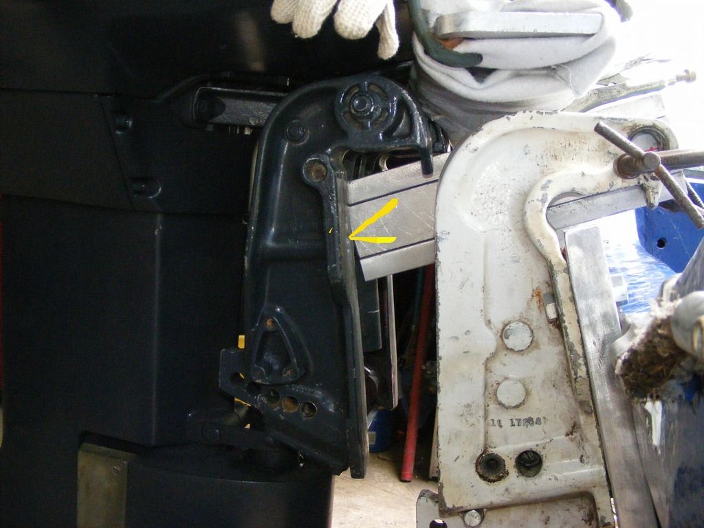
The duh huh is that different applications will be different. The base plate mounting holes (to transom) have been altered and mine is at least 1.5" lower than factory. Black lines --- Top is where grinded for clearance of top pivot bolt. It has to go in first and still be able to turn - for plate function and to thread through back plate. Tighten with fingers, pliers, and wrench. It's a 3/4" bolt, but doesn't take much torque.

Middle line - had to notch the mounting flange for t/t to lay flat. Note - this thing will not be supporting much of anything as it was designed; I have considered drilling numerous holes in the mounting brackets for weight reduction, but....... doubtful I'd realize two pounds difference for all the work?

Bottom black line is where I opened up that slot side ways for bolt alignment into existing tapped hole. Was a bottom cross brace hole; bottom cross brace is the flatbar just stuck there - am starting to figure on "how to position the landings for trim rods"......

Chartreuse line - had to grind/file down flanges for fit between mounting plate. She was a tad wider after bolting t/t back in. Only took approx 1/8" each side


Looking like I'll be able to tilt further than practical; can't be certain until.... I know for fact I'll be cutting the tits off below the trim cylinders and I may or may not drill some holes just because, but I'm not an engineer and can't be certain of how much strength it'll lose or how much it needs - obviously less.
Removing the CMC cylinder and my Volvo pump offsets most of what I am adding back.

"IF" any of you engineering types LOL could figure out "how much/where etc" to lighten up those Johnson brackets :facepalm:
PS: all of this takes more than a minute without a drill press, plasma cutter, etc etc, and NO HELP!!!
 

jrttoday

Lieutenant Junior Grade
Joined
Feb 8, 2010
Messages
1,081
scratch the last few posts... going a different route, but still plan to use that t/t. Not sure it was warranted, time will tell..... bought 150 cu ft of Argon, bottle and all. Had gauges, bought wire, will have to see if I have much call to weld aluminum after this side project?
$20 to refill it and wire isn't that bad, just you don't get much mileage with either.
Almost started a new thread, but am scattered enough!!! lol

Looks like I have to wait until Monday to get my questions answered about welding cast aluminum to aluminum plate - have welded a LOT of aluminum plate (MIG), but never cast aluminum. Watching stuff on Youtube isn't the same and I can't find anything on point.

While swapping steering tubes, I got two more brackets and another Raker, 22p for free !! The prop probably needs a new hub, but weld repair for sure; it's trash if she can't turn it once I have trim that works and the motor raised a "little" bit more :facepalm: :lol:...... somebody, stop me, lol

I have enough plate to not use the cast at all; just being lazy and not wanting to line bore for steering tube, plus extra cutting pieces of plate for gussets/reinforcement etc. PLUS, might have to have a machine shop do it ($$$$$ and how backed up they are lol)

**** HAPPY FATHER'S DAY!!!!!!
 

jrttoday

Lieutenant Junior Grade
Joined
Feb 8, 2010
Messages
1,081
it's only what I didn't address while running the 100 horse. I was OK with not running like a wild banchi before, but that 115 is giving me a different feeling; plus having the time now... Forgive me for thinking out loud lol, I "might" lol be doing some questionable things here, but they sort of make sense to me :lol:
If anyone has some input, yea or nay or go ahead wild man, it's your behind hanging out there!! :lol:

I can weld cast, but lots of cutting back out welds due contamination in casting. "Molded" aluminum, different story... (and the brackets I was going to use, which are they? doesn't matter, too much work involved to use them as planned). With TIG, I could pause long enough to burn impurities out, but, you'll never get them all.

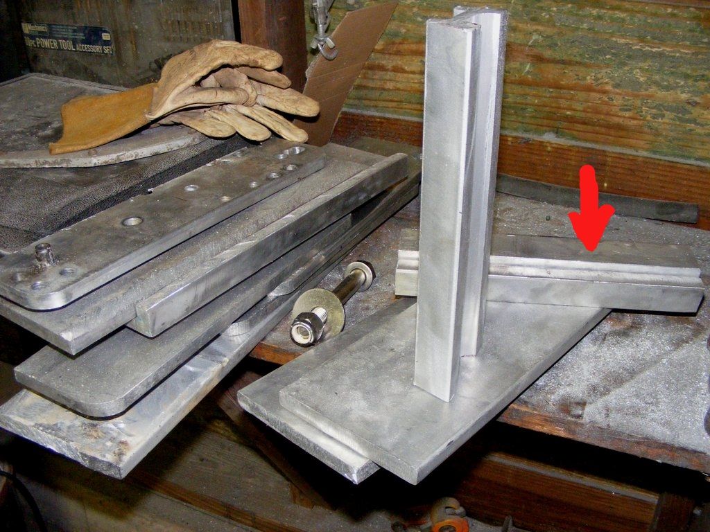
Found 22 usable inches of that molded piece for two 10.5" arms which will be welded to 9/16" plate somewhere near top. Red arrow pointing out strip to be welded in back side for extra strength and giving me 1" for steering tube bushing landing (motor t/t swivel). Strip has to be beveled to fit flush first. Ends with hole will be wrapped with 1/4" for additional support. Plan to cut through plate for arms to be back welded. And gussets under arms to be back welded as well.

I have to check measurements (prolly hang the motor in the air for easier transfer of info) in marking holes to be drilled etc - for me, that's the best way to be certain of accuracy. The combination of rulers, center punches, and drills have been known to LIE!!! :lol:

8.5" from the front of the hole for steering tube shows me close to where I was running with the CMC; and now, I'm looking at increasing that to 9.75ish" - which isn't much but something. If I have a concern, that's where it is; I'm not increasing the offset externally, but internally. Might put a leash on the motor just incase....... :facepalm:

http://


PS: aluminum on the left is cut up CMC (except for the bottom piece, which is also 9/16" scrapyard material), plus a few pieces on the floor - the rest is from the scrapyard. 5/8's SS bolt (have four) to be used through transom. Yes, I'll be filling bottom two holes and redrilling for 5/8's just because I'm moving bottom holes 3/4" closer to the top.
Feedback, comments, concerns - what am I not seeing?

AND this'll keep me busy for a few days...... lol
 
Last edited:

sphelps

Supreme Mariner
Joined
Nov 16, 2011
Messages
11,475
Sorry my welding experience is limited to about a half hour of tinkering in the back yard so not much help here ...:facepalm:
But I can cheer ya on or egg ya on surely enough !
Go man go !!!! You got this under control !!!:watermelon:
 

jrttoday

Lieutenant Junior Grade
Joined
Feb 8, 2010
Messages
1,081
^^^ LOL my experience with welding is mostly from the neck down!! It wasn't about intelligence, just didn't want the additional headache(S!!!!)
I chose straight argon because it's hotter and my Lincoln is only 180 amps; but amperage is not so much a factor as voltage with alum. And my machine is yet untried with aluminum; and these pieces are thick. Mixed gas usually gives a tad more penetration depending.... and with less smoke, depending again...
depending upon the operator, machine, and thickness of; wire dia too. OMG gas pressure.... get the picture? Jacking your welds is prettier, but I won't be doing that; not as strong....

But Cindy is southwest of here and we're catching a lot of rain (like that's any different than usual); aluminum, like fiberglass, doesn't like high humidity.
While sitting and watching the rain, got to thinking on "how much torque" IS RIGHT THERE!!!! It's not a lack of confidence in my welds, but in the strength of aluminum - been working carbon steel way too long!! Probably be backing a few spots up with bolts if I can? we'll see.

BIG SIGH........... !!!!!! just checked, looks like we'll be socked in for a week or so??? MIght be able to bolster some rafters in back of garage, hang the motor with the bow out to do it like I want. My side garage is in the process of getting a tin roof, so that's out. Need to knock out the wall and..........

Cutting this stuff with 6" cutting wheel on grinder or Sawzall is about the same - slooooooow! But with Sawzall, it's important to wait until your body is vibrating in harmony with the Sawzall :) Needless to say, I should be done cutting slots and drilling holes in ????? who knows how long?

PS: for anyone switching their machine from fluxcore to weld aluminum - clean your liner or get a new one's best!! Lots of impurities in dat snake
 

jrttoday

Lieutenant Junior Grade
Joined
Feb 8, 2010
Messages
1,081
didn't know that when I delete pics on Bucket, they're gone here too LOL!! Oh well, wasn't liking that crap anyway flawed design. "If at first you don't succeed, keep on sucking til ya do succeed" - Curly :joyous: As much as I try not hurry and make mistakes, it happens; when venturing into the unknown or "I haven't tried that yet...."
Usually, I try to think things through and that's where I am at - or "this pic" is where.

http://[URL=http://s173.photobucket.com/user/jrttoday/media/DSC000031_zpsxwsvq6ho.jpg.html]


In a mock fit up, I don't waste time/effort etc on deburring excessively, cleaning, or making the exact fit. It's only to see what needs what to be what I have in my mind - I have a rough sketch on paper, but.... that's all I need
And I need an 1" thickness on the steering tube end (has to be ground down more). I have 3/4" SS bolts w/1" shoulder from the CMC, probably use them for added holding those strips in place (peace of mind) - have seen too many good aluminum welds fail, that shouldn't have. There'll be a lot of stress in there, sideways, up/down etc.

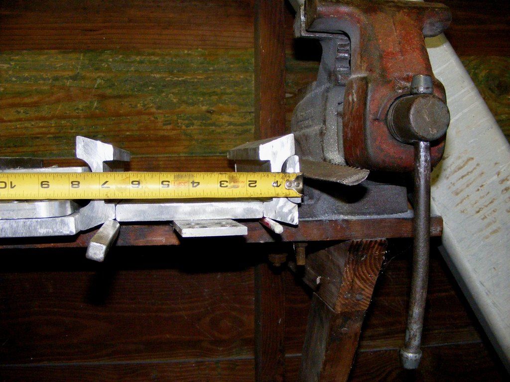
7.5" is tight between the brackets; probably shoot for slightly less; which means the plate needs to be cut back some more, but will need to have both arms just about finished first. The plate could go on top to achieve desired width, but that would diminish overall strength - beveled and butt welded (back gouged too) is the way to go. A few braces across the bottom for stability and have to figure out exactly where the trim rod should mount[/URL]

BTW, it's upside down for this. Another thing, ALL welding, or as much as possible, needs to be completed BEFORE holes are made for steering tube. Aluminum, especially, is known for distorting etc. A jig would be nice, but even then.... I may or may not fashion some sort of jig with that 2.5"x6" tubing against the wall and use a Mercury steering tube (if I can still get my hands on it?) because it's slightly larger than my Johnson tube, yet slightly smaller than the bushings - then I'd be able to finesse the holes for the bushings
We shall see how it goes but there's a chance I'm looking at a machine shop :lol:
 

Pcolafisher

Petty Officer 2nd Class
Joined
Jun 26, 2013
Messages
188
I would add a couple of concerns. To cut aluminum, I would use a carbide saw/blade. Second, I would recommend a spool gun instead of a new liner I'd at all possible to pull instead of pushing aluminum through the welding cable/lead. Great decision on the argon, anything else would put bubbles in your milkshake (weld).
Cheers
 

jrttoday

Lieutenant Junior Grade
Joined
Feb 8, 2010
Messages
1,081
Pcolafisher yeah you right; and I appreciate the input for sure. However lol, kind of having to make do with what I've got. Could've cut it with my Milwaukee couldn't find a 36 tooth blade locally and didn't want to wait; had blades and wheels. Plus, I don't have an easy way to lock it down and still cut safely with a circular saw. - which is the main reason.

Truth be told, might as well be working out in a Bacca field.... was sweeping water out the door all day :sorrow: ha, just having fun

Have welded with a spool gun, not my favorite. My Lincoln is year old and on my second 10lb spool, about 8lbs remaining, rollers in great shape, ten foot whip.
Only place I've ever welded aluminum, we had Miller's with 30' whips; of course, another drive motor on the gun. Going to at least try mine as is. We mostly used Argon/Helium 75/25; and that welds sweet!! and pricy!!
I WILL try a test piece before this humidity moves; just don't feel like chasing moisture every time I strike an arc, got a few days....

But really!! THANKS! no know-it-alls here lol. You see my slagsaw wedged between the vise holding the strip in place - carbon steel/pipe welder. That some why we post, so somebody else can point things out. Working alone out in the garage, radio on, and the most popular song today was the EBS Warning going off several times an hour!! :lol: Guessing y'all got a bit too? haven't seen the News yet....

That last post of mine today is a perfect example :facepalm: really, no shame here. The plate laying down was cut (1 of 2) for the motor to bolt to. Just stuck it in there cos it's close to the size I need.
 

Pcolafisher

Petty Officer 2nd Class
Joined
Jun 26, 2013
Messages
188
JR, Let me know how it works with pushing aluminum. I might try it instead of TIG for some work. I'd really like a spool gun. I understand working with what you have. The rain in Pcolafisher has finally stopped!
Cheers
 

jrttoday

Lieutenant Junior Grade
Joined
Feb 8, 2010
Messages
1,081
this is why no hurry... yet!!

http://

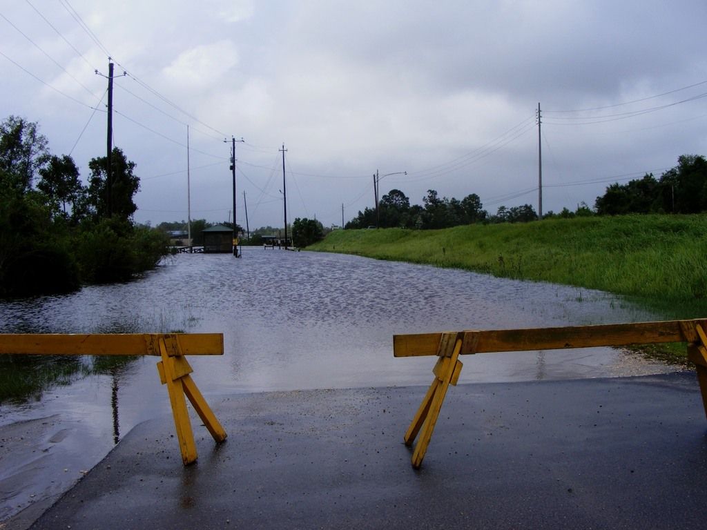
stopped raining for an hour or two, the ramp's about even with the last tree in the middle. If I was going to go, I'd a moved the barricades and launched right there; just not jones'n that bad LOL. (as the crow flies, about a mile from me)
There are people that can draw things out and be dead on and there are others that "think" they can!! lol I am neither, that's why I do it this way... and still wrong sometimes, oh well.

But I need some input here. I can jam those brackets tight (or snug) and just let them wear in, or leave 'em loose? Probably need a little gap between the arms and brackets towards the rear anyway - for clearance. The steering tube will prevent it from misalignment while underway; and am doubtful of much flex after plate across the top/braces across the bottom.


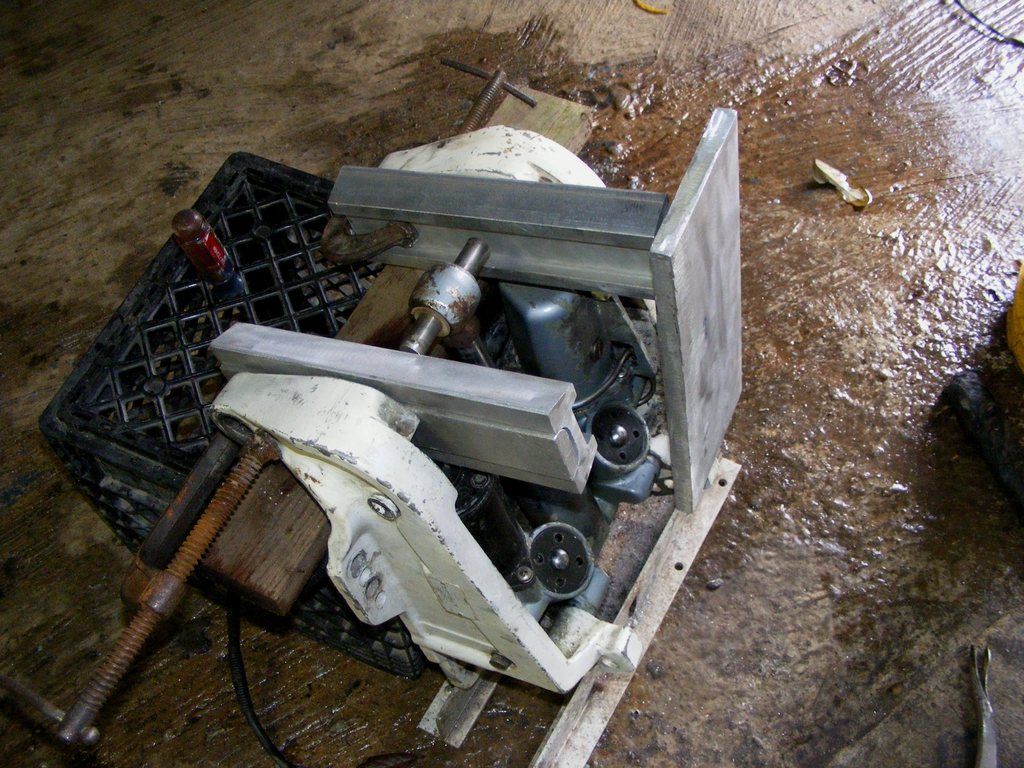
Plate (vertical) just sitting there, one each side for motor to mount - just like it normally would to transom. They are 9/16 thick and 5x13 long; will also be tied together, no certain how yet. Holes to fit arms for back welding, arms also to be gusseted. (aluminum or not, I'll be curious to see what this monster weighs lol).

Have to get brackets with t/t back on the boat see how the rest goes exactly. Trim cylinder pin, where I need to position arms through plate to attain correct??? lol heighth.

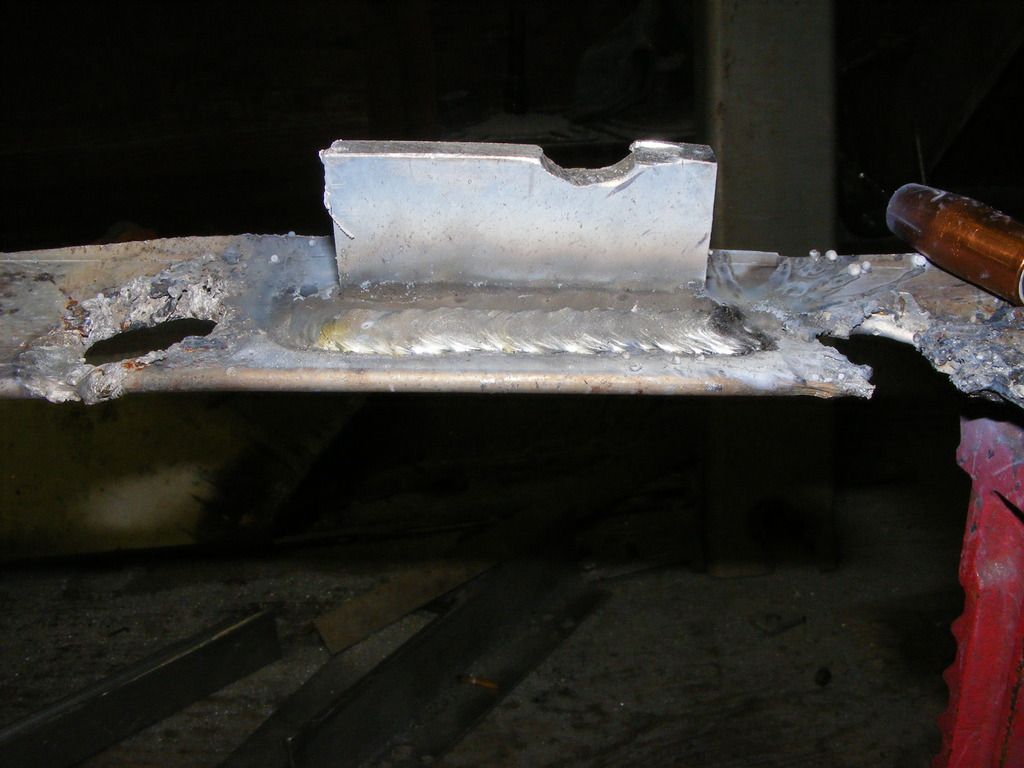
AND FINALLY!!! put your dark glassed on!! nothin to brag about here, just showing it works. Points to notice - was mostly trying to see "how much metal I "could" carry with this machine. With thicker aluminum, make your beads smaller with multiple passes. CLEAN the crap out of it!! WITH acetone (what I would use) first, before using STAINLESS STEEL wire brush (I prefer toothbrush size) - didn't here, it's scrap.


not going to waste a bunch of gas, wire, material, and time just trying to make a pretty weld that's trash anyway. I found out just about everything I need to know in four inches of weld (which includes wrapping the ends). Humidity is real high!!!, metal was filthy and only hit it with Tigerpaw, and had a fan stirring the air for my comfort - all of that sort of meant I might could've gotten away with a little less gas pressure. Was running 25cfh.

For those that don't know, do not confuse gas pressure with cleanliness - gas is not flux. Also, my Lincoln has a toggle switch for use of their spool gun; to use it w/o, simply switch polarity on the machine - two wing nuts and swap wires. Set wire tensioner as LIGHT as possible; had mine set to where the knob would just stay on - last thread or two.

It's important to keep your whip as straight as possible; I had a slow bend in mine and up off the floor, and then to my work - no problem. However, cannot attest to different machines OR different settings. For the thickness of the pieces welded, the bottom was 1/4" and upright 1/2"; had my machine maxed out on wire feed and heat. NO COMPLAINTS!!

Bottom line... that's one sorry weld.... worthy of the trash. It could be cleaned up though, cold lap ground out, wire brushed, spit shined LOL. not on my watch...

PS: initial measurement, it's looking like 7" offset from transom when done; whenever that is....
 
Last edited:

jrttoday

Lieutenant Junior Grade
Joined
Feb 8, 2010
Messages
1,081
maybe I should also say that's "continuous welding" as in did not stop to allow plate to cool, nor clean between welds. If you'll notice smoother appearance on left and rippled progressively worse towards right; plate was heating up, causing me to have to "jack" the weld. It is NOT OK to douse or spray aluminum in/with water to cool unless it's trash to begin with. Let it cool naturally; a fan is the most I'll ever use, but really? how big a hurry are we in? won't buy ya much...

"Cold-lap" along the bottom is caused primarily from moving too fast - in this instance, plate was too hot. BUT!! believe it or not, even the USCG or Navy will buy that weld "IF" the cold-lap is cut out, it's brushed free of smoke and clear from spatter, there's no porosity, and the weld size is within tolerances of the materials joined.
 

jrttoday

Lieutenant Junior Grade
Joined
Feb 8, 2010
Messages
1,081
my bad; terminology is rusty, been 2yrs since being around aluminum. It's called "incomplete fusion" or "I F" and not cold-lap. Cold lap is a form of I F and usually caused by too much wire feed for the voltage being used - looks kinda pot belly-ish. Cold lap should be removed completely; most other forms of I F can usually be repaired without much work.
Lots to do before I can actually weld something :clock:
 

Pcolafisher

Petty Officer 2nd Class
Joined
Jun 26, 2013
Messages
188
JR, Considering the equipment you were using, that weld looks awfully nice! I figured you.d have problems even feeding the wire. It must due to the new liner. Goof job! Cheers
 

jrttoday

Lieutenant Junior Grade
Joined
Feb 8, 2010
Messages
1,081
Goof job!
IS CORRECT!!! :lol::lol: you know the saying...... "we the willing, have done so much for so long with so little for nothing.....we are now qualified to build anything from nothing" or it goes something like that.
I have a new liner BUT in trying to take the old one out, the first two inches broke off. Heck with it for, not a lot of fluxcore's been through it - just blew it out for now.

What I'm seeing that the pic won't show - it "should" be OK with smaller beads like you're supposed to anyway; but the "arc force" just isn't there with this small a box. On material of this thickness, I think" I was running 24 to 30+ volts - been awhile and can't set voltage other than by letters on my box anyway...

However, I am getting good penetration; and that, I can see also.
Backing up a minute, too much going on around here to stay on top of everything but trying to stay on top before committing to one way or another. Looked at a few different motors, three had a thick bushing between arms and brackets; guessing others had a thin nylon washer like I found with steering tube and brackets I'm using.

Bought several SS washers I'll be using in addition to nylon for spacing between brackets. Not there yet, but am thinking + or - 3/16" each side. Haven't built yet, but cannot foresee much of any flex in whatever this thing is? lol
 

jrttoday

Lieutenant Junior Grade
Joined
Feb 8, 2010
Messages
1,081
Mr speedo typo here, couldn't type fast enough... lol
EDIT/PS: haven't had the problem, can't say for certain. Perhaps, people are settin their wire tensioners too tight? Aluminum wire is very soft compared to fluxcore or MIG; and will easily take on shape of rollers. It'll twist or flatten out some making it more difficult going through the liner INMHO. Like said, mine is set as light as possible - and would go lighter if I could.
We'd push 30' of 035 before it made contact with drive rollers in gun. With a new plastic liner, you could often push more as it piled up in the floor (state of the art Miller equipment though) :D
 

jrttoday

Lieutenant Junior Grade
Joined
Feb 8, 2010
Messages
1,081
Tuff few days of figuring.... I guess it's going to be like this, or real close.
Was 2&7/8's before; shooting for 3.5" this go round. She was getting near the threshold before with a moderate load - I never run WOT with a heavy load anyway.

http://[URL=http://s173.photobucket.com/user/jrttoday/media/DSCF0008_zps7atmqcjl.jpg.html]

Plan is - I have 1/2" spacer behind brackets to transom right now; will be welding 1/2" plate from top to bottom underneath brackets. the back plates to motor brackets will add nothing to distance - being through plate for back weld. [/URL]
Need 1/2" plate for clearance of bolt heads on through transom - has nothing to do with going to 5/8ths bolts. Can't mount new brackets high enough as is.

Will be able to lower 3/4" by moving two bolts and loosening two nuts at the ramp, but back up means a trip home. Nuts on the exterior slot for bracket adjustment; leaving 5200 intact; top bolts are through steel. Not putting turnbuckles on this.

Plate to be perpendicular to arms for downward trim..... or did I just miss something??? That's something I need investigate further or somebody steer me in the right direction - physics is not my strong suit.... Off hand, I "think" the trim needs be set about where she'll run at WOT? Or will it not affect l/u measurements in relation to height on the lower end of that spectrum? Measurements I wish I'd taken.

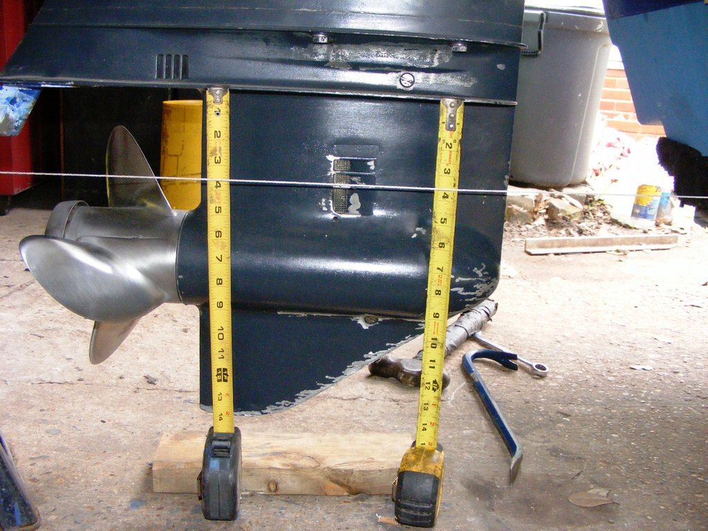
Tape measures just hanging on the lip; all in all, looking like 7" offset but a whopping 29.5" from hull to where the leading edge starts on the prop. Have minimally increased the distance of offset CMC provided, not sure about the other; added a few pounds and took some off, but certain she's a couple heavier.
(see where I vaselined before painting and didn't get the skeg thoroughly clean of oil either; didn't want paint on the screen or plugs LOL)


[[[[[pretty clean for a 1970 original paint job under the hood, nothing much has really been touched - washed with soap and water two years ago]]]]]]
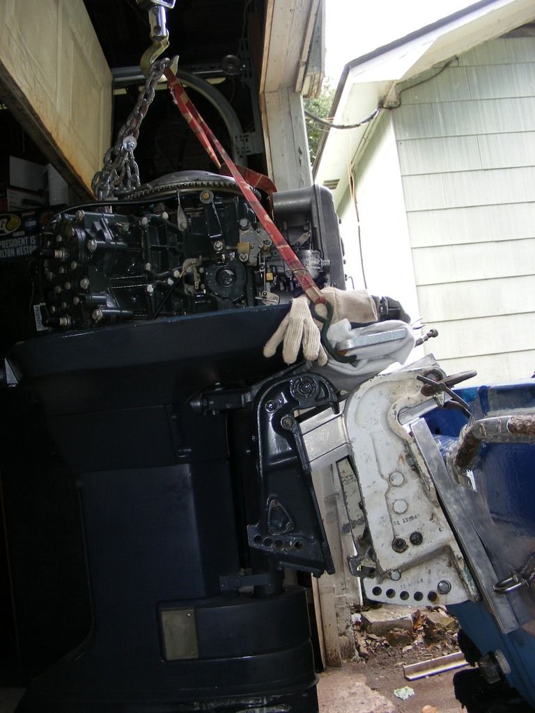
The glove liners I couldn't find all winter being used as a buffer, now that we're bumping 90 lol. But do ya see what I'm looking at? I have "some" adjustment in the brackets on the motor, and in this pic, those brackets are trimmed all the way down. Smell the smoke? I'm thinkin lol.

Not welding yet cos I'm still ironing....... things out!! If I push those arms up (as in trim) before locking the back plates. However they go, still have clearance for through bolts on motor bracket; especially this one (each side).


I can "THINK" I'm on the verge of answering my own question; but like she says, "If you have one more thought, your head's going to explode :lol: !!!!"
PS: I'm going this high to start because in looking down the creek, it will be easier for me to cut back than to add to; but there I go thinking again. lol Thanks for any help....... :)
 

jrttoday

Lieutenant Junior Grade
Joined
Feb 8, 2010
Messages
1,081
That was all I needed to do - step back from the problem and LOOK!! Sitting on a 5gal bucket with my face buried in there, wasn't seeing... Had to deviate from I "thought I wanted and what would work best".
Simply moved motor brackets back to 3rd hole and pushed the arms up in line with them - if that isn't perfect, we're going to say it should've been lol. Just means I won't have any height adjustment on back plate - which I really don't need, have enough on forward brackets.

pardon me for thinking out loud, but I like to think things through as much as possible while remaining flexible - build and design, figuring it out as I go. It's the only way my two brain cells work. THANK YOU!! Iboats and everyone here.

Glass Guy came by yesterday and started talking about repainting my cowling etc, but his airbrushes and compressor are toast. "WHY?" I ask; he figures I'm tired of hearing the static about it being green. "Why?" again; maybe I'm too old school, not going to spend time, money, and effort just to please other people. It isn't camo, but it blends right in with the rest of the boat and a predominant color of the swamp. Eventually, I'll paint the emblems and put 'em back on, that's about it.
There's a ton of people on here with amazing looking stuff; and I AM IMPRESSED!!! but that isn't me..... am just trying to do a job...
 

jrttoday

Lieutenant Junior Grade
Joined
Feb 8, 2010
Messages
1,081
guessing y'all can relate; not a clean or uncluttered surface anywhere!! And just because you have nothing to work with, shouldn't mean you can't do anything. Am waiting for Iboats to to demote for posting some of this junk :rolleyes:
I had to replace the liner today, just not in the way you'd think. I must have thought I was back at my old work welding aluminum because we leave the neck loose so you turn it 360*; broke mine :lol: Good thing I'd bought the extended.... Had to twist the nozzle to make it weld, got tired of that!!
Suffice to say, not much welding was done

http://

Just as well, bottom fell out as I was leaving and had to put it all in the cab. I say that because the humidity is way high in the garage and I'm having to bump up gas pressure - air is thick!!

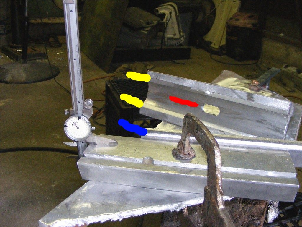
Was trying to do this today, however........


1" thickness before welding, should be right at it after. Nylon bushing has 1" depth, if it's off some, it can be adjusted by filing and/or welding.
Blue line is where the strips were ground/beveled to fit inside and give me 1".
Yellow lines point at where channel was beveled for weld. Bevels made with Tigerpaw (flapper wheel) on grinder
Red line at notch - done on both pieces of channel, 9/16" drill bit on press with overlapping holes; strips to be plug welded

At least I should be set to weld some tomorrow??? lol
PS: the half hole in the one strip got in my way!!! Happens when using scrap
 

chevymaher

Commander
Joined
Mar 29, 2017
Messages
2,932
LOL that is fairly neat compared to what i got going on right now. Between boat interior engine and outdrive. Chevelle parts strewn everywhere.
 
Top