engine and out drive installation...

rickasbury

Senior Chief Petty Officer
Joined
Jul 13, 2011
Messages
790
So, I'm getting close to getting back in the water after what a year and a half....I have the rebuilt transom assy ready to go back on and will bring the boat home I hope tomorrow and install that on Sunday. I had a leak through the seal on the gimbal ring. So, I'm going to install the transom assy and just the out drive and poke it back in the water to test and make sure the leak is 100% resolved before I put the motor in. In preparation for the final install of the motor and the Bravo III out drive....I did the bellows earlier this year and a coupler was replaced just prior to that. When I did the bellows, I did the gimbal bearing but had difficulty getting the out drive back on. I had the alignment tool and thought it was aligned OK until a friend came over to help....he said you had to "align" the bearing a bit which he dit working the alignment tool back and forth a bit until it slid in and then the outdrive went on- now that I have had the motor and transom out, no way it will line back up. Should my alignment now be 100% motor mount adjustment or a combo of :"aligning the bearing" and the motor, just was not clear on that....also, on the outdrive, where the front mount for the trim cylinder goes through that is a nylon piece that either allows the drive to go a little further down or in the other position, not as much down....what is it supposed to be on my out drive??
 

harringtondav

Commander
Joined
May 26, 2018
Messages
2,450
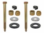
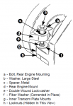
You may have to do both. Be sure to get the fiber washer and lock washer under the rear mounts, and tape the nuts into their pockets.

Visually rough in the front mounts using a 1" O.D. rod or pipe. You can also engage the alignment tool in the coupler but just short of the gimbal brg& observe the clearance around the tool.
 

rickasbury

Senior Chief Petty Officer
Joined
Jul 13, 2011
Messages
790
Got ya on the first part, lost me on the second. Have only removed a motor, never installed one.The alignment tool I have is 3' long so it is not going "short of the bearing"- not sure I understand what you would gain by doing this anyway? So the motor mounts on the inner transom plate should control the left to right.....the front motor mounts are the up and down.....so for the left to right I can see "aligning the bearing" a bit.....have I got it??
 

harringtondav

Commander
Joined
May 26, 2018
Messages
2,450
The alignment tool's front dia engages the coupler splines I'd - minor dia and the gimbal brg id at very close clearance. The distance from the end of the splines to the face of the gimbal brg is about 12". If you engage the coupler only the tool or 1" rod it will give you an idea where the front of the engine is pointing. The rear mounts control rear engine height and center.

The front mounts have a slotted hole that allow 1/4 to 3/8" max side movement. The engine must be dead aligned between the coupler and the center of the gimbal gimbal brg.

The gimbal brg may move in it's hsg during installation, so you may need to square it up to get the alignment tool to pass.
 

Maclin

Admiral
Joined
May 27, 2007
Messages
6,761
The 1" rod is more like a probe, use it to rough-in the front mounts up-down setting before using the more precise alignment tool. When I had rear mount issues I used one to see where I was at when I could not get the tool to go in. It showed me the rear mount on one side had collapsed on the fiber and double-wound washers. You may get the mounts close enough to use the tool first try.
 

achris

More fish than mountain goat
Joined
May 19, 2004
Messages
27,468
No alignment on the rear mounts. If you're out of alignment on left/ right, then you have a transom thickness variation problem.

On the rear mounts, just silicon the fibre washers to the inner transom plate, put the double wound spring washer inside the fibre washers and the nuts in their pockets on the lower side of the mount. Now just lower the engine down onto the rear mounts. Put the spacers on the bolts and grease them up nicely, slide them through the mounts in the engine flywheel cover and tighten to spec (35ft-lb). You must tighten the rear mount bolts before attempting the alignment. If you don't, the double wound spring washers doesn't get compressed and the alignment will always appear high, or you won't get the bar in at all.

Chris....
 

rickasbury

Senior Chief Petty Officer
Joined
Jul 13, 2011
Messages
790
double wound spring washer....I took the boat somewhere to have the motor pulled with a forklift...I was right there and he handed me the long bolts, the nuts were taped into the inner plate as described...I have the fiber washers as described but I sure don't remember any other special fasteners but will look again. The boat had very low hours on it when I bought it but keep seeing little things that tell me this is not the first time it has had the motor pulled...
 

rickasbury

Senior Chief Petty Officer
Joined
Jul 13, 2011
Messages
790
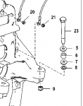
ah....I don't have that double wound lock washer....here is my set up ow251759 engine serial number.....so the bolts were still in the motor.....there was the bolt, a fiber washer and the spacer- when I look at the parts detail for this serial number, none of the descriptions say fiber washer, all say aluminum? Also, all these parts can't go on the top side of the mount, don't some of the washers go behind the nut?? transom plate.gif5,6,7 and 8. It does not show that doble wound lock washer and does not show what goes where like what is shown above.....surprised there are tha many variations!
 

Rick Stephens

Admiral
Joined
Aug 13, 2013
Messages
6,118
Rick,

Hard to tell with the small picture, but it surely looks like the right hand side bolt stack is exactly what I posted a picture of with the double wound washer at the bottom.
 

rickasbury

Senior Chief Petty Officer
Joined
Jul 13, 2011
Messages
790
I probably can't post the link to the site I got that off of...it is a mercruiser parts site and when you go into the detail to order the parts, there is nothing that looks like that and there are detailed pictures of each, or supposed pictures of the items anyway....so your saying there are no variations and my 2006 should be as pictured? On the site, you go by the engine serial number...guess I will have to just order the parts to make sure. Again, not sure if this had been taken apart and not put back together correctly, it will be when I'm done!
 

Rick Stephens

Admiral
Joined
Aug 13, 2013
Messages
6,118
Ah, that serial number comes up for a Bravo 3 drive, not an engine. Here's a larger screenshot of the parts page you showed. No coil washer:

Screen Shot 2018-08-28 at 11.16.11 AM.png
 

Maclin

Admiral
Joined
May 27, 2007
Messages
6,761
When I blew it up from the web page it got a little fuzzier, looked like the ol' double wound, maybe a bit flattened... :faint2:
 

rickasbury

Senior Chief Petty Officer
Joined
Jul 13, 2011
Messages
790
so Rick, some have the washer and some do not? If you found that on a parts site then you would have been able to look at each part like I did and do not see a "coil washer" or what ever you call it?? And how did you blow that page up?
 

achris

More fish than mountain goat
Joined
May 19, 2004
Messages
27,468
Later engine mounts, including yours, are longer and don't use the double coil washer. A nice change that does make the whole process slightly easier, but boy, Merc created some serious confusion when they did that! :facepalm:

Chris.....
 

Rick Stephens

Admiral
Joined
Aug 13, 2013
Messages
6,118
so Rick, some have the washer and some do not? If you found that on a parts site then you would have been able to look at each part like I did and do not see a "coil washer" or what ever you call it?? And how did you blow that page up?

So I searched for that serial number and came back with Bravo outdrive parts. The site I went to when you mouse over the exploded diagram it blows up the area you are hovering on, then hit the keystrokes that allow a selected screenshot. No blowup at all.

I did not know that later model Mercruiser motor mounts did away with the coiled washer. Probably a good idea as the coils would add in a degree of variables that would add to pressure on the coupler. My ignorance stems from a serious lacking in the financial capabilities to be owned by late model holes in the water.
 

rickasbury

Senior Chief Petty Officer
Joined
Jul 13, 2011
Messages
790
Well, to add to the confusion, I look again and there IS that coil washer....I'm totally mistaken. The only reason I would think you would want that there is so that you can adjust the front mounts, gives the motor a pivot point if you will to go up and down with out binding on the mount? They were I'm pretty sure not there- when the motor was pulled I brought the boat home and cleaned everything out, the bilege is clean and they were not there...... coil washer.jpg Sorry for the confusion....my coupler went once already, I will order them, thanks all.
 

rickasbury

Senior Chief Petty Officer
Joined
Jul 13, 2011
Messages
790
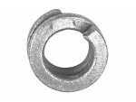
So, got that ordered last night....in the bag of parts for my inner transom plate I have two of these washers....they do not fit on any of the studs for the mounting of it, the impression of the nut you can see seems to match up to one of the nuts but there are only two....I tried to bag stuff as I took things apart so I would not forget where stuff goes....not so much on these two washers..they are thin and aluminum I think...any clue where they go? Washer.jpg
 
Top