Tagged’s 140 Johnson Resurrection

Tagged

Petty Officer 2nd Class
Joined
Jul 10, 2012
Messages
123
Thanks for the compliments, guys. It was quick, but it wasn’t a full rebuild, just a resurrection.

And I’m not done yet. Still to come:

- three wiring circuits: tilt/trim, jackplate, and bilge pumps
- trailer leafsprings
- hull leak repair.

Then I can take it to the water for a real test. I’m sure to find other issues. Further down the line I know I still need:

- all new navigation lights and circuit.
- all new trailer lights and circuit.

So, I agree, I may never be done.
 

spybot

Chief Petty Officer
Joined
Jul 4, 2016
Messages
504
Lol yeah buddy we a never done. Are going to keep this thread (but it has done what it said)
One for the wiring and one for the hull repair.#
Im good with the glass so let me know if you get stuck. Wiring is easy enough too.
Andy
 

Tagged

Petty Officer 2nd Class
Joined
Jul 10, 2012
Messages
123
Yes, I’ll keep going in this thread. Thanks for the offer on glass help, but this hull is aluminum.

My leaks appear to be the result of pitting on the top (inside) surface of the hull skin. The boat has a second welded-in deck on top of the ribs, so I can’t access the inside of the hull skin.

I’ll notice a pinhole leak, and discover that it’s really just the bottom of a pit that’s 1/4” or bigger. I probably find about a dozen pinholes like that each year. If I don’t stay vigilant, I might not discover them until they’re already grown to 1/4” holes. It can get out of hand quickly, and it’s why I run double automatic bilge pumps.

Since i can’t access the inside of the skin, my repair technique is to rough up the exterior surface, peen a dimple 2-3 times the size of the hole, fill the dimple with JB waterweld, and sand smooth. I’ve got about a 90% success rate. The failures appear to be from inadequate sanding, allowing the water to pull the patch off while underway. The smooth ones rarely fail.

I’m always looking for better techniques, so if anyone has a better idea, I’d love to hear it. I’ve considered using the Bondo that includes fiberglass reinforcement, beacause it should be much easier to sand. But I don’t know how waterproof that stuff is.

Any ideas?
 

spybot

Chief Petty Officer
Joined
Jul 4, 2016
Messages
504
I cant help with the Bondo i have never seen the stuff never mind work with it.
The JB weld is really good stuff. As you know its all in the prep work. The stuff is awesome. Maybe think about either cutting into the deck easy way to get to the holes and just pop rivet it back on. Its just the same as us guys with the fibreglass. You have the hull then a sheet of marine ply which is glassed over, so to get to the problem just cut a hole then patch it when job is done. Thats the basic's a lot more to it but you get the jist
Andy
 

Tagged

Petty Officer 2nd Class
Joined
Jul 10, 2012
Messages
123
Electrical question: (sort of)

The ‘96 donor motor used SystemCheck, but I never had compatible gauges. The ‘new’ ‘82 motor, obviously, did not. I’d prefer to use the 96 remote control, because the reversible handle works better for my center console. (The 86 kill switch button doesn’t appear to be reversible.)

Here’s the question. Is the wiring to the warning horn the same, so that the overheat warning horn will still work? I can’t figure that out from the wiring diagrams.
 

spybot

Chief Petty Officer
Joined
Jul 4, 2016
Messages
504
Iam sure the over heat will work. Is it not the same wire for all the crossflows ?
 

Tagged

Petty Officer 2nd Class
Joined
Jul 10, 2012
Messages
123
You're probably right. I question it because of the 2 second "chirp" at startup on the newer controller. It seems to be computer generated, testing the system on each startup. The 82 motor doesn't have the system check, so I thought it might be wired differently. It looks like the best way to check will be to go actually check. I'll do some direct confirmation testing this week, before launching this weekend. I'll post back here with what I find.
 

racerone

Supreme Mariner
Joined
Dec 28, 2013
Messages
38,433
The horn itself has a wee circuit that sounds the horn as a " self test " when 12 volts is applied to it.
 

Tagged

Petty Officer 2nd Class
Joined
Jul 10, 2012
Messages
123
Minor testing tonight did not result in any chirp from the 96 horn. I think the horn is faulty. I blame it for the 96 motor burning up.

If I have time before dark tomorrow, I may try to put the 82 horn in the 96 control box, otherwise I’m fabricobbling a way to use the 82 controls.

BTW, looking at parts diagrams, the 96 motor might have had a 95 control box. Hard to tell.
 

Tagged

Petty Officer 2nd Class
Joined
Jul 10, 2012
Messages
123
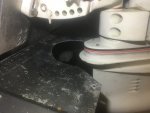
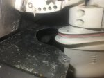
Click image for larger version  Name:	CA91EDB9-9F0E-4BFA-AB75-7DB217DDF048.jpeg Views:	2 Size:	2.25 MB ID:	10533562 How much clearance should there be between the front of the lower unit and the hull?

My boat has a horizontal plate attached to the back of the transom, to direct water flow out of the tunnel. I'll try to get a picture tonight. The 82 motor either sits closer to the transom, or it tucks further under, because when it is tilted all the way down, it contacts that plate. The '96 never did. I need to trim the plate, but how much do I trim? Will the motor "flex" under power, or is it enough just to clear the plate at rest?

in the photo, the motor is trimmed all the way out. It’s actually on the tilt ram. If I trim it down, it makes hard contact with the plate.
 

Attachments

  • CA91EDB9-9F0E-4BFA-AB75-7DB217DDF048.jpeg
    CA91EDB9-9F0E-4BFA-AB75-7DB217DDF048.jpeg
    2.3 MB · Views: 0
Last edited:

Tagged

Petty Officer 2nd Class
Joined
Jul 10, 2012
Messages
123
Ok, duh. How about I just put the pin in the secon or third hole?

Yeah, that would do it.


😄
 

Tagged

Petty Officer 2nd Class
Joined
Jul 10, 2012
Messages
123
Bam! Another win.

The 82 horn doesn’t “fit” the 96 control box, but it works. So I installed it anyway, for the testing this weekend.

I’ll order the right horn later.

I also transferred the 82 T/T switch housing onto the 96 handle, to replace the cracked parts we’ve been putting up with for 10 years or so.
 
Last edited:

Tagged

Petty Officer 2nd Class
Joined
Jul 10, 2012
Messages
123
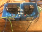
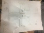
The beginning of the relay boxes: two home improvement electrical boxes, bolted together with two headless #10 stainless bolts. The bottom becomes the positive terminal in each box, the top is the negative.

The left box box has the relays for the T/T, the right box is the jackplate. Each has two pairs of green/blue wires still to connect. The light gauge is to the switches, the heavy pair goes to the motor.

I’ll bolt the boxes to the to the inside of the transom, beside the slashwell, and run power from the battery to these terminals, and join the green/blue wires with soldered butt joints. All joints, including the ring terminals inside the boxes, get coated in silicone and then heat-shrink tubing. I’m determined to win the battle against saltwater corrosion.
 

Attachments

  • photo284421.jpg
    photo284421.jpg
    2 MB · Views: 0
  • photo284423.jpg
    photo284423.jpg
    1.7 MB · Views: 0

jimmbo

Supreme Mariner
Joined
May 24, 2004
Messages
13,639
Putting the pin in the second or third hole will work, just make sure there is enough clearance to allow for the movement in the lower motor mounts. There were/are less flexible lower mount available for engines used in Hi Performance applications.

Regarding using silicone on the wiring connections, a lot of silicone sealers are slightly acidic and that may cause some corrosion issues. Liquid Rubber(neoprene) might be a better choice. If you're just using the Silicone to seal a wire entrance point to your junction box, and the insulation is intact, there shouldn't be an issue
The warning/alarm horn could be moved to a location on the dash, that will guarantee you will hear it over all other noises
 

Tagged

Petty Officer 2nd Class
Joined
Jul 10, 2012
Messages
123
Ok, headed to the creek this weekend. I spent the day today finishing the rest of my list, most of it was wiring.

Tomorrow is is the big day. Wish me luck.
 
Top