Looking for some help here. Back story:
Had a DTC 0174, Adaptive Learn Bank 2 High fault. Engine went into limp mode.
Thinking it might be an injector issue (broken/stuck/clogged), I replaced the injectors, all of them just to be safe.
After resetting the code and leaving the ECM unplugged for some time to clear the limp mode, the codes are now gone and limp mode 'seems' to be gone. However, when I run the engine past 4300 rpm the high pressure fuel pressure drops from just over 2000psi to 24psi. Targeted and Actual throttle position remain high. Again, no codes. Seems like limp mode, kinda. Left the ECM unplugged for 7 days, no codes and same issue. Limp mode still active somewhere? Hard to believe. So . . .
I checked the HPFP pressure vs rpm with the Workshop manual chart. All good up to the point of failure.
Now I'm thinking the system is somehow fuel starved at higher RPM's. So, I ran the engine from a seperate gas can/fuel source, same issue. I've replaced the low pressure fuel pumps and fuel filter (and tested the pressures, all good). I've replace the high pressure fuel pump twice, same issue.
So, unless I missed something, it's not a fuel system issue.
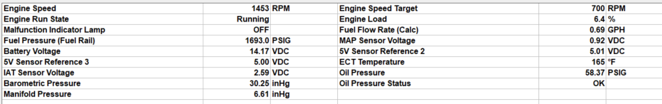
At this point I'm thinking there is math inside the ECM that determines the output for the Fuel Rail Pump signal to the high pressure pump. That math is made up of information from 7 (I think) sensors. Looking at all of them with the Diacom software, only the ECT and Oil Pressure sensors seemed a little off. So I replaced them. Signals look better, but still no codes, still same issue.
Tested continuity from the High Pressure Fuel Pump signal to the ECM, all good. Not opened or shorting to ground. Even put an oscilliscope on the Fuel Rail Pump signal and it looks good (PWM signal increasing with RPM's).
Open to any suggestions on what to try next.
Is there another way to reset limp mode?
Am I missing something simple here?
Thanks in advance,
Biz
Had a DTC 0174, Adaptive Learn Bank 2 High fault. Engine went into limp mode.
Thinking it might be an injector issue (broken/stuck/clogged), I replaced the injectors, all of them just to be safe.
After resetting the code and leaving the ECM unplugged for some time to clear the limp mode, the codes are now gone and limp mode 'seems' to be gone. However, when I run the engine past 4300 rpm the high pressure fuel pressure drops from just over 2000psi to 24psi. Targeted and Actual throttle position remain high. Again, no codes. Seems like limp mode, kinda. Left the ECM unplugged for 7 days, no codes and same issue. Limp mode still active somewhere? Hard to believe. So . . .
I checked the HPFP pressure vs rpm with the Workshop manual chart. All good up to the point of failure.
Now I'm thinking the system is somehow fuel starved at higher RPM's. So, I ran the engine from a seperate gas can/fuel source, same issue. I've replaced the low pressure fuel pumps and fuel filter (and tested the pressures, all good). I've replace the high pressure fuel pump twice, same issue.
So, unless I missed something, it's not a fuel system issue.
At this point I'm thinking there is math inside the ECM that determines the output for the Fuel Rail Pump signal to the high pressure pump. That math is made up of information from 7 (I think) sensors. Looking at all of them with the Diacom software, only the ECT and Oil Pressure sensors seemed a little off. So I replaced them. Signals look better, but still no codes, still same issue.
Tested continuity from the High Pressure Fuel Pump signal to the ECM, all good. Not opened or shorting to ground. Even put an oscilliscope on the Fuel Rail Pump signal and it looks good (PWM signal increasing with RPM's).
Open to any suggestions on what to try next.
Is there another way to reset limp mode?
Am I missing something simple here?
Thanks in advance,
Biz