@Lpgc thank you for taking an interest in this issue, more eyes looking at a problem always help. You can look at the files if you want. Just go to rinda.com and click on the updates tab. Click the button next to Diacom and then click the download button. This will let you install Diacom software and you can view any .rec files. This is all free, if you want the extras like the service manuals and the harnesses to scan an engine, that costs extra.
Rinda taught me this when I was at a Very remote lake and the customer attempted to help me, but instead he knocked my laptop into the water. Customer used his satellite phone and downloaded Diacom to his Laptop and used my cables to finish the diagnosis and get him running again.
I would be very interested in your opinion.
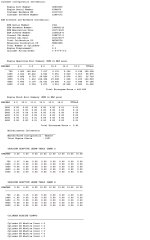
Thanks, I will download Rinda and have a look at the files. I already attempted to look at the files by importing the data to a spreadsheet, doing that I can see a lot of the header and summary information but I didn't get as far as being able to read what I believe will be the live / realtime data in the files.

There has been talk about injector PWM not seeming to change much with engine load. I've converted DI engines to run on LPG using electronics which intercept the petrol injector PWM signal to calculate a PWM for LPG injectors. The petrol DI injectors can open and close much faster than LPG injectors and petrol DI injectors can be opened/closed several times during one induction cycle, the LPG injectors open/close much slower so the LPG ECU has to 'add up' the total pulse time of petrol injectors during a single induction cycle to calculate a total petrol injector pulse duration to base a single LPG injector pulse duration per intake cycle on.... If the PWM of petrol injectors doesn't seem to change much for different engine loads it may be partly because the petrol fuel dose depends on the pressure in the high pressure rail and partly because DI petrol injectors can be pulsed more than once per induction stroke (or even during the compression stroke) - The PWM pulse lengths might not change but if there are twice as many pulses there'd be twice as much fuel delivery if the high pressure rail stayed at the same pressure. The DI injectors might even do multiple pulses per induction cycle and individual pulses not be the same length, if they're not the same length live data readings might only show the average or longest pulse length, but even if individual pulses were the same length live data might not show total pulse length per induction stroke (total being pulse length X frequency per induction stroke). For a given rail pressure we'd expect 2 x 2ms pulses to deliver twice as much fuel (4ms total) as 1 x 2ms pulse (2ms total) but live data might show 2ms in both cases. In which case 1 x 3ms pulse (3ms total) would deliver 3ms total, but if we don't take account of number/frequency of pulses per cycle it would seem to us that the 3ms were delivering more fuel than the 2 x 2ms pulse when actually it's only delivering 3/4 of the 2x2ms (total 4ms) pulse. And this isn't even accounting for variable rail pressure. Interpreting how much fuel a DI system is delivering is complicated, especially if there's more than 1 pulse per cycle and live data doesn't reflect total pulse length per intake cycle... even before taking rail pressure into account. How much a given 'ideal' injector (ideal being open/close time not being affected by pressure) will flow depends on the square root of pressure x pulse time... Abstract (not including any unit terms) examples would be some random injector fed with 1000psi (square root close to 33) pulsed for 3ms delivers 99 'units' of fuel, the same injector fed with 2000psi (square root close to 45) pulsed for 3ms delivers 135 'units' of fuel, or the same injector fed with 2000psi pulsed for 2 ms delivers 90 'units'.
Last edited: