1988 125 HP Force Rebuild

Sandy-man

Petty Officer 2nd Class
Joined
Aug 10, 2019
Messages
104
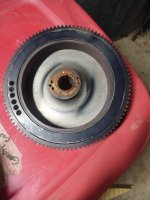
I began a rebuild on my 125 HP Force motor back in 2020, had to replace the cylinder block because it overheated real bad resulting in scored cylinder walls. The previous owner had it rebuilt too, which included boring cylinders to max oversize.

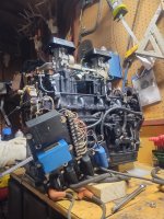
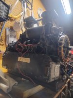
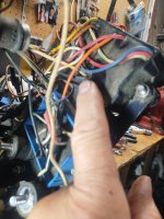
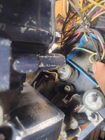
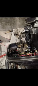
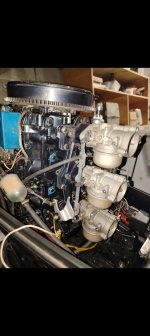
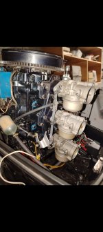
Many life experiences got in the way after tearing it down and finding all the parts I needed, so I had to put the rebuild on the back burner, WAY back burner. Now I'm back at it and have the engine block put back together, head is on, carburetors are on. I got to a point where I needed to refer back to all the pics I took of the motor before I started tearing it down and several during the process. Unfortunately for me, I can't find anything other than some pics of the wiring.

I was hoping someone on this forum has the same motor and, if you don't mind, able to take some pictures of the 3 sides excluding the head side. This would help me a great deal with finishing putting it back together.

I would greatly appreciate any help anyone could offer, even if it is simply websites that may have photos or diagrams I could refer to.

Thank you!

Hi, JerryJerry05, I've gotten plenty of help from you in the past, mostly prior to the tear down.
 

Sandy-man

Petty Officer 2nd Class
Joined
Aug 10, 2019
Messages
104
If anyone is able to provide me with some pics of their motor, please also include the throttle linkage and mechanisms. Thank you in advance.
 

Sandy-man

Petty Officer 2nd Class
Joined
Aug 10, 2019
Messages
104
Attached is a few pics of the 125 HP motor I am currently working on and having issues with figuring out where some wires should hook up. I also made a short video and hope it's not too large to post here.

This motor has 2 C-D units, they are from 2 different manufacturers so the wires are not all the same color, unfortunately. Anyway, all the wires except for one on each of the two are all hooked up where they belong as I did not have to detach them during the tear down process. This one wire from each of the C-D units are located in the same spot so I'm almost convinced they serve the same purpose. Please see pics and hopefully short video. For the life of me I cannot figure out where they are supposed to hook up. Both are too short to reach the port side where there are a few empty spots on the terminal block that is on that side. The terminal block that is located right next to the coils and C-D units is all filled up, no empty spaces where these wires might go. The service manual says the white wire is supposed to go to the e terminal block and thee black wire next to it is supposed to go to ground. One of them has the white wire but the other has a black with yellow stripe wire that is located in the same spot as the white wire on the other unit, see the last two pics on the right side below. The video won't upload, unfortunately.

I am lost with regards to these two wires and could really use any help or suggestions anyone may have.
 

Attachments

  • IMG_20260620_192631763_HDR.jpg
    IMG_20260620_192631763_HDR.jpg
    1.5 MB · Views: 2
  • IMG_20260620_192642849_HDR.jpg
    IMG_20260620_192642849_HDR.jpg
    1.1 MB · Views: 2
  • IMG_20260620_152953211_HDR.jpg
    IMG_20260620_152953211_HDR.jpg
    1.3 MB · Views: 1
  • IMG_20260622_135432541.jpg
    IMG_20260622_135432541.jpg
    1.5 MB · Views: 1
  • IMG_20260622_135415140_HDR.jpg
    IMG_20260622_135415140_HDR.jpg
    1.3 MB · Views: 2

Sandy-man

Petty Officer 2nd Class
Joined
Aug 10, 2019
Messages
104
Oh, one other thing I forgot to ask. When the motor overheated and shut down in the middle of Lake Erie there was never any sign that it was overheating, no alarm of any sort. The motor just suddenly started slowing down while on plane, dummy me, at this point I pulled back the throttle and pushed it full forward again and she took off for a few seconds and then shut down completely. I have to believe that there is supposed to be an alarm of sorts for this. If so, what sends the signal to the alarm as I have to believe that it is faulty or the alarm or wiring to the alarm?
 

Nordin

Commander
Joined
Jun 12, 2010
Messages
2,707
There should be a sensor mounted in the head.
A orange wire goes from the sensor to the terminal strip.
It is a sensor not a sender, it is a bimetal and when to hot it short out to the block (ground).
OEM the sensor is connected to a horn but can be connected to a indicator light.
 

lgaytan

Petty Officer 1st Class
Joined
Jul 15, 2015
Messages
230
Here a few other pics from mine, are you planning to replace the flywheel? It might vibrate if broken?
 

Attachments

  • Screenshot_20260623_074205_com_hihonor_photos_SlotAlbumActivity.jpg
    Screenshot_20260623_074205_com_hihonor_photos_SlotAlbumActivity.jpg
    386.9 KB · Views: 1
  • Screenshot_20260623_074159_com_hihonor_photos_SlotAlbumActivity.jpg
    Screenshot_20260623_074159_com_hihonor_photos_SlotAlbumActivity.jpg
    462.1 KB · Views: 1
  • Screenshot_20260623_074154_com_hihonor_photos_SlotAlbumActivity.jpg
    Screenshot_20260623_074154_com_hihonor_photos_SlotAlbumActivity.jpg
    456.4 KB · Views: 1

Sandy-man

Petty Officer 2nd Class
Joined
Aug 10, 2019
Messages
104
There should be a sensor mounted in the head.
A orange wire goes from the sensor to the terminal strip.
It is a sensor not a sender, it is a bimetal and when to hot it short out to the block (ground).
OEM the sensor is connected to a horn but can be connected to a indicator light.
Thank you, Nordin, I appreciate it. I thought that might be what it is. I don't know why my book wouldn't spell that out for me, but it doesn't. I will just replace it and follow the corresponding orange wire from the boat wire harness. I'm assuming the alarm or light can be tested with a jumper wire from the battery.
 

Sandy-man

Petty Officer 2nd Class
Joined
Aug 10, 2019
Messages
104
Here a few other pics from mine, are you planning to replace the flywheel? It might vibrate if broken?
Yeah, I either will need to find a replacement or take it to a machine shop where they might be able to balance it by drilling a hole out of the steel ring on the opposite side, like it appears the manufacturer did.
 

Attachments

  • IMG_20260623_132841885.jpg
    IMG_20260623_132841885.jpg
    1.4 MB · Views: 0
Top