1979 Champion Bass Boat - Tear Down and Restoration -- with PICS

DHag

Petty Officer 2nd Class
Joined
May 29, 2007
Messages
166
Re: 1979 Champion Bass Boat - Tear Down and Restoration -- with PICS

Clamping the Plywood

What you use to clamp the plywood isn't so important, as long as the plywood is flat and the clamping pressure is fairly even. As you'll see, I invested in a highly expensive clamping system, to ensure that it was properly clamped.

The instructions on the adhesive said that for wood, apply the adhesive to only one side. So once I had the glue spread on one piece, I flipped it over, lined up the edges, and set them together.

As I predicted, the two boards did not mate up in the center because of the slight warp they had developed.

Here I have placed the plywood/glue sandwich on my clamp's base, which is perfectly flat and will not bend under pressure.
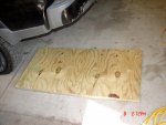
12-DSC05831.JPG

Now I apply the pressure plate to the plywood, centering it. The pressure plate is cast steel, in 1/4" X 1-1/2" segments. It will force the plywood perfectly flat when pressure is applied, without any deformation.
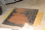
13-DSC05832.JPG

Finally, the clamp mechanism is used to apply approximately 1200 pounds of clamping force. It's quite an expensive clamp system, but it has many other uses, so I think it was worth the price. :D

The adhesive instructions say to keep the pieces clamped for 24 hours. I will likely leave it for 48 hours, just to be sure.
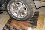
14-DSC05833.JPG
 
Last edited:
DHag

Petty Officer 2nd Class
Joined
May 29, 2007
Messages
166
Re: 1979 Champion Bass Boat - Tear Down and Restoration -- with PICS

Sorry for taking so long to post again. Got sick for a week. Then I slipped on some rocks while fishing for smallmouth along Iowa's Middle Raccoon River. Slammed my shin down hard on a big rock. Yeah, it left a mark. Then, budget and time got in the way. Anyway....

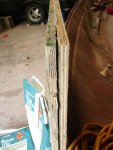
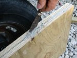
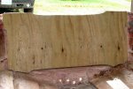
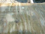
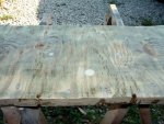
Turns out the gluing job didn't work out as good as I had hoped. The steel grate wasn't as rigid as I thought, and the edges of the boards were able to separate a little while the PL dried. Here's a view of the worst side. I put a lot of thought into how I could salvage this.

1.JPG

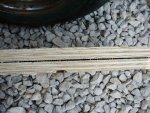
The glued boards measured 24" X 48". The transom measures 19" X 45". I made the first rough cuts to 20" X 48-1/2". I just shaved the "better" edges, then made the larger cuts on the "worse" edges. Here is the worst side after cutting.

2.JPG

The first step was to lay a bead of PL along the gap.

3.JPG

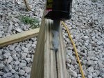
Next, I used a thin, flexible putty knife to spread the PL. I worked the PL lengthwise and crosswise, pushing the goo into the gap as much as possible.

4.JPG

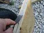
Then I used the putty knife to work the PL down between the boards. Repeating these two steps worked the PL deep into the gaps.

5.JPG
 

DHag

Petty Officer 2nd Class
Joined
May 29, 2007
Messages
166
Re: 1979 Champion Bass Boat - Tear Down and Restoration -- with PICS

Here's the "worst" edge after working the PL into the gaps as best I could.

6.JPG

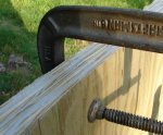
I applied a C-clamp and squeezed the boards together. Look closely and you can see that some adhesive has squeezed out, indicating that I have worked the adhesive between the boards. Even though this was the "worst" edge, after cutting the gap wasn't very deep.

7.JPG

Since the wood is pressure treated, it requires stainless steel (or otherwise special finish screws). These are #8 X 1-1/2" stainless steel, exactly the thickness of the transom boards.

8.JPG

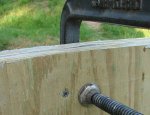
I put the screw in next to the clamp. I failed to take a picture after removing the clamp, but the adhesive remained squeesed out after the clamp was removed. The screw kept the gap pulled together.

9.JPG

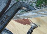
Finally, here's the opposite edge. It was worse than it looked, as I was able to work the PL into the gap a full four inches. But again, here's proof that I got it worked deep down into the gap, as there is a lot that squeezed out.

10.JPG

I did this process all the way around the boards, working the glue into the gaps and pulling the gaps together with the clamp and holding them with screws. I'm now letting it set for two days before doing more. I'll include a pic or two of the finished boards once they adhesive is fully set.

Next step, final cuts to fit the new wood into the outer transom skin.
 

Woodonglass

Supreme Mariner
Joined
Dec 29, 2009
Messages
25,929
Re: 1979 Champion Bass Boat - Tear Down and Restoration -- with PICS

DHAG, No offense but... I'm really concerned with your transom lamination. PL is really not a good way to lam up the two pieces of wood for the transom. TiteBond III wood glue and wood screws would be a much better method. I would dry overnight and you can remove the screws and fill the holes with PB when you install it in the boat. The transom is one of the MOST critical parts of the boat and it really needs to be strong. I'm fearful that this is not the case with yours. JMHO.;)
 

DHag

Petty Officer 2nd Class
Joined
May 29, 2007
Messages
166
Re: 1979 Champion Bass Boat - Tear Down and Restoration -- with PICS

DHAG, No offense but... I'm really concerned with your transom lamination. PL is really not a good way to lam up the two pieces of wood for the transom. TiteBond III wood glue and wood screws would be a much better method. I would dry overnight and you can remove the screws and fill the holes with PB when you install it in the boat. The transom is one of the MOST critical parts of the boat and it really needs to be strong. I'm fearful that this is not the case with yours. JMHO.;)
First off-- No offense taken. Your opinions are certainly worthwhile.

I ran this boat for four seasons with a transom and stringers that were of the strength and consistency of soggy cardboard. No signs of cracking or weakness. I wasn't surprised to find rot in the top corners of the transom where the wood was exposed to the open air. But I was surprised to find rot all through the transom when I drilled some test holes.

I'm not sure what the boating industry thinks, but in the flooring industry there seems to be a division of opinion as to Titebond vs construction adhesives like PL. The main difference there seems to be about water-based vs solvent-based, and cleanup. Durability and strength seem to be comparable to them. But that's another area.

Anyway, the way I'm doing it will make the transom a thousand times stronger than it has been. It's a wood that will never rot. Plus, I have added stainless steel screws, and they will stay. No need to remove them. Plus the transom will be "clamped" between two sheets of 1/4" stainless steel when I reinstall the motor lift plate and bolt the motor on.

Let me add a disclaimer: To all readers of this thread: The methods I am using to rebuild my boat may not be in accordance with the latest boat-building standards. But they are well-researched and decisions are made based on my own experience in construction, the results of my research, and limitations of my budget. You may do as I do, but that may not be the best course. I welcome all opinions and feedback. I encourage readers take the opinions and input from other experienced boat builders very seriously.
 

DHag

Petty Officer 2nd Class
Joined
May 29, 2007
Messages
166
Transom - Hull Sanding

Transom - Hull Sanding

Had to take some time off to deal with the generalities of life, budget, and time. Finally got a chance to move forward some more on the transom.

I was about to generate a LOT of wood and resin dust, so I set up my highly specialized dust control system: a big fan and an open garage door. Worked great!

01-DSC05860.jpg

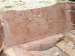
Here's my starting point. Lots of old, bad filler around the transom shell.

02-DSC05862.jpg

https://sphotos.xx.fbcdn.net/hphotos-ash3/180250_429598080396948_865351727_n.jpg

03-DSC05863.jpg

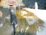
After first sanding with 36 grit disc on my angle grinder. Most of the old, bad filler is smoothed out.

04-DSC05864.jpg
 

DHag

Petty Officer 2nd Class
Joined
May 29, 2007
Messages
166
Transom - Hull Sanding

Transom - Hull Sanding

Sanded the last wood layer off the outer transom shell, and finished the outside edges.

06-DSC05868.JPG

Safety, safety, safety! See that little red spot beneath my fingernail? That's what I got from a 7-inch sanding disc spinning at 19,000 rpm, when it exploded. All that was left was the bit around the hub. If I had not been wearing proper safety equipment (gloves, safety glasses, dust mask), that little spot would most definitely be stitches at the least, if not a lost finger tip.

05-DSC05865.JPG
 

DHag

Petty Officer 2nd Class
Joined
May 29, 2007
Messages
166
Transom - Fitting the Wood

Transom - Fitting the Wood

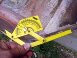
Measuring the angle of the transom to the sides of the set-back.

07-DSC05870.JPG

End of transom board, cut to fit the set-back angle.

09-DSC05873.JPG

First length cut. 1/2" longer than transom shell. Ends notched to match approximately the bevels in the side walls.

08-DSC05871.JPG

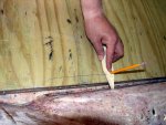
Here's my high-tech tool for marking the line for the bottom cut. A piece of lath wood, cut to a point. Drill a hole that will hold a pencil snugly, located up from the point a distance equal to the longest space (on the left in this picture).

10-DSC05874.JPG
 

DHag

Petty Officer 2nd Class
Joined
May 29, 2007
Messages
166
Transom - Fitting the Wood

Transom - Fitting the Wood

I used a sabre saw to cut the bottom edge. It was set at a 12-degree angle to match the transom's vertical angle.

12-DSC05876.JPG

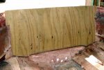
After final cut on the ends, fitting the ends to the sidewall bevels. Just a little fine trimming was needed at this point to make sure the wood fit tightly against the transom shell, with minimal clearance on the ends and bottom.

13-DSC05877.JPG
 

DHag

Petty Officer 2nd Class
Joined
May 29, 2007
Messages
166
Transom - First Drilling of Holes

Transom - First Drilling of Holes

With the wood clamped in position in the transom shell, mark the required holes.

14-DSC05878.JPG

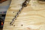
The best tool I could come up with to drill the holes. My grandfather's brace and bit set, which is older than me. Quality tools are truly timeless.

15-DSC05879.JPG

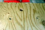
Holes were drilled as marked, but every hole is 1/4" larger than it needs to be.

16-DSC05880.JPG
 

DHag

Petty Officer 2nd Class
Joined
May 29, 2007
Messages
166
Transom - Sealing the Wood

Transom - Sealing the Wood

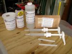
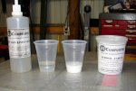
I bought my epoxy supplies from US Composites on-line. Great quality and great prices. Exceptional service. Left to right: Cab-o-Sil thickener; epoxy hardening catalyst; epoxy resin; measuring pumps.

17-DSC05882.JPG

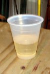
The epoxy is to be mixed 3 parts resin to 1 part catalyst. This is a 16-ounce cup with 3 squirts resin and 1 squirt catalyst. Mixed and ready to apply. "Pot life" in the cup is about 20 minutes at 80 degrees.

18-DSC05883.JPG

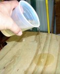
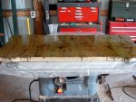
I laid the wood on a sheet of plastic, on top of my table saw, which is a very flat surface. The epoxy won't sick to the plastic sheet. Just pour the epoxy onto the wood.

19-DSC05884.JPG

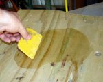
I spread the epoxy using an old plastic auto body filler spatula. Just keep pouring and spreading it out until it stops soaking in. No hurry. Once out of the cup, the "working time" is two to three hours.

20-DSC05885.JPG
 

DHag

Petty Officer 2nd Class
Joined
May 29, 2007
Messages
166
Transom - Sealing the Wood

Transom - Sealing the Wood

One batch of epoxy (3 squirts resin, 1 squirt catalyst) was exactly what was needed to saturate one side. Two-day process to do both sides.

21-DSC05887.JPG

The guide I read said to mix equal parts Carb-o-Sil and resin. That turned out not to be thick enough. I ended up adding twice as much Carb-o-Sil to thicken the epoxy to what I wanted for filling the holes. Thoroughly mix the resin and catalyst as normal, then mix in the Carb-o-Sil.

22-DSC05888.JPG

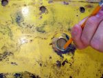
The holes filled with thickened epoxy. These will be sanded smooth. After the transom is finished, the holes will be re-drilled to the correct size. This will leave a 1/8" wall of epoxy around the holes, sealing the wood from any water that gets in around the motor mounts.

23-DSC05889.JPG
 

DHag

Petty Officer 2nd Class
Joined
May 29, 2007
Messages
166
Transom - Sanding Epoxy

Transom - Sanding Epoxy

Today I had a few minutes free before having to do some mowing, so I decided to sand the epoxy. I had read that epoxy was hard to sand, but I think that was probably talking about sanding by hand.

The epoxy must be sanded so the epoxy adhesive used to install the wood will adhere with maximum strength. I needed to smoothe the hole filler, take off some drips, and prep the surface. I used my angle grinder with a 60-grit sanding disc.

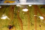
With first grinding, it was obvious there was going to be a lot of dust. See the light-colored, sanded areas? This looks like bare wood, and I was concerned I was going too deep.

1-DSC05891.JPG

Here is the first side, after sanding. Upon closer examination, I could see that, yes, it was "bare" wood. But the wood is saturated with epoxy that penetrated into it. So even though the wood is exposed, it's still sealed.

Also, when the wood is glued into the transom shell with more epoxy, it will be fully coated and sealed even more.

2-DSC05892.JPG

Opposite side after sanding. Ready to glue into the transom shell.

3-DSC05893.JPG
 

DHag

Petty Officer 2nd Class
Joined
May 29, 2007
Messages
166
Gluing in the New Transom Wood

Gluing in the New Transom Wood

I struggled with the question of how I was going to clamp the wood in place in the transom while the epoxy hardened. I've seen lots of different ways guys have clamped the transom. Big wood clamps. Home-made wood clamps. Steel braces across the transom held with pass-through bolts.

I considered a combination of C-clamps and boards jammed between the transom and the front rib that 's still in the boat. I also thought about how I could rig some metal braces. But then I got another idea.

Somebody may well say I'm nuts for doing it this way. But I'm used to that. I hope the method to my madness becomes apparent.

Here's a screw that I stuck into an existing hole that goes through the outer transom wall. It was from a fish-finder transponder mount. You can see that there are several holes like this in the transom wall.

1-DSC05894.JPG


I decided I would go ahead and drill out this hole so the screw would pass through. The I chose five more locations to do the same, using existing holes where I could. This made a total of six evenly-spaced holes for screws, three across the top, and three across the bottom.

Then I took another drill bit, just slightly larger than the screw heads. It used it to counter-sink each hole. Here is a shot of where I tested the counter-sink with a screw. The top of the screw head is just slightly below the surface level of the transom wall.

2-DSC05895.JPG


By now you see what I did. I used screws to "clamp" the wood in place while the epoxy hardened. Here's my reasoning:

  • There are several holes in the outer transom outer wall already. I have to plug and refinish them. Might as well use some of them.
  • Both the transom outer wall and the wood are flat. I checked them both with the straight edge of a four-foot level.
  • I can't think of any better way to pull the two parts together evenly than with a set of stainless screws.
  • When I refinish the hull, I'm going to apply new gelcoat. So these screws will be sealed by the epoxy adhesive; covered and sealed over the top with fairing compound; coated with a new finish of gelcoat. Solid, sealed, and invisible.
 

DHag

Petty Officer 2nd Class
Joined
May 29, 2007
Messages
166
Gluing in the New Transom Wood

Gluing in the New Transom Wood

I read on an epoxy and fiberglass supplier's web site that it took basically a 1:1 mix of resin to Cab-O-Sil to make a peanut butter consistency. Well it took a lot more than a 1:1 mix to get the expoxy mixture this thick. It was more like 1 part resin to 3 parts Cab-O-Sil.

When the epoxy is thickened like this, it will stay where you put it, even on a vertical surface.

At the upper right is the 3/16" notched trowel I used to spread the epoxy.

523426_432566483433441_996196319_n.jpg

This is how the epoxy looked after spreading with the 3/16" notched trowel. I applied the epoxy to both the wood and the inside of the transom outer wall in the hull. I had already sanded the wall of the hull. I wiped it down with acetone, then applied the thickened epoxy to it the same as I did to the wood, as shown here.

4-DSC05898.jpg
 

DHag

Petty Officer 2nd Class
Joined
May 29, 2007
Messages
166
Gluing in the New Transom Wood

Gluing in the New Transom Wood

I set the wood in place in the shell, and drew it up tight with six stainless steel screws, through the six counter-sunk holes that I drilled earlier.

The piece of black tape is over a hole that did not get filled completely. I pushed some epoxy into it, then put the tape over it to be sure it could not run out.

562841_432566563433433_1461530622_n.jpg


Here is an edge-on view, showing that the shell and wood were pulled up tight by the screws. No gaps. Also, epoxy was squeezed out of all the holes in the outer shell. I'm confident I have full contact between outer hull shell and wood, with no air or unglued spaces between them.

553936_432566596766763_969566531_n.jpg


Turns out that I had EXACTLY ENOUGH epoxy and Cab-O-Sil to get the wood glued into the hull. (See the empty bottle at bottom right?) As shown, I applied epoxy to both parts. I also had just enough to lay a wide "bead" down the sides and across the bottom. There was a little left to finish filling the gaps around the outside, almost. You can't see in the pictures, but there are a few small gaps around the edge to fill yet, but the wood is secured all the way around.

I have some automotive glass-reinforced polyester resin. It's too thick to use for layup, but will be perfect to use to fill the little gaps and finish the edges a nice fillet. Then it will be ready for laying in
 

DHag

Petty Officer 2nd Class
Joined
May 29, 2007
Messages
166
Re: Gluing in the New Transom Wood

Re: Gluing in the New Transom Wood

Quick update. I'm now in the process of calculating a materials list for the stringers and ribs. I'll try to make good posts on my measurements and calculations.

Hopefully, that will be enough to keep followers from thinking I've quit.

Then it's get the money set aside in the budget to order them. I've discovered there are two ever-present bugaboos in a project like this. Money and time.
 

DHag

Petty Officer 2nd Class
Joined
May 29, 2007
Messages
166
Weight and Cost -- YES! Foam-core stringers are MUCH lighter than wood!

Weight and Cost -- YES! Foam-core stringers are MUCH lighter than wood!

Well, I've crunched the numbers.

All the "experts" on the Internet say something like "carefully remove the old stringers for use as a pattern." Yeah, right. :facepalm: At the start of this thread, I showed that my old stringers were mush.

When I cut out the deck, I left its edges around the hull. To measure the stringers (and to create new ones later), I stretched a string across the hull from the old deck edges, and measured straight down from the string to the hull. Then I subtracted the thickness of the deck. I did this foot by foot from the transom forward to the front bulkhead, up the chine lines inside the hull. (The old stringers were laid in the hull chines.) Plotting this out on computer let me produce these patterns:

Layup.jpg

There are three pieces in this pattern that are marked "outer stringers." When I use these to make new stringers, those three "outer" pieces will be combined into one piece. Also, note I have one rib piece labeled "1 original, 2 optional for extra strength." Triton boats have built a reputation for being exceptionally stiff. Their web site is very open about how they do it, and the main thing is an extra rib. I figure, while I'm in there, why not?

To get the "square feet" measurements, I laid out the image above in Paint.NET software, and drew it out with the resolution set to 10 pixels per inch. So if I drew a straight line (easy to do) that was 100 pixels long, that's 10 inches. I just drew straight lines point to point for the measurements, using the editor to tell me the dimensions. Then, fill in the shapes with black. Then use the "magic wand" selector to select a black area. At the bottom of the screen you see the area in pixels. That first section measured 57,800 pixels. 10 pixels per inch is 100 pixels per square inch. 57,800 divided by 100 is 578 square inches. Divide that by 144 (12" X 12" in a square foot), and you get 4 square feet. I rounded the results of all calculations "up" for glass materials estimating.

With these measurements, now I can put to rest the oft-debated question, "Do you save weight using foam for stringers instead of wood?" The most common thought is since foam core stringers require an extra layer or two of glass laminate for strength, you lose whatever weight advantage you might get from foam.

Well, that's not quite true.

Using information from BoatDesign.net, here are the results for my boat:

Wood-core stringers, original layout, laying up
two layers of CSM/1708 as instructed by WoodOnGlass: 89.4 pounds

Foam-core stringers with extra rib, laying up
three layers of CSM/1708: 28.4 pounds

I found this from a senior member of "The Hull Truth Forums:" "If you are considering 2lb urethane foam as just a form over which to lay your glass and the glass has sufficient stiffness without the foam, then urethane is fine. Four layers of 1708 or 1808 biax is usually stiff enough up to about 18" in height."

My tallest stringer is only 8 inches, so three layers is more than sufficient, though I wouldn't do just two layers.

So, to summarize:
Wood: 89.4 pounds
Foam: 28.4 pounds
Overkill foam (4 layers CSM/1708): 36 pounds


That's a savings of 61 pounds using foam cores, WITH an extra rib added. (53 pounds with "overkill") That's enough to bring my boat's total weight under 1000 pounds. Or, put another way, that's a 6% reduction in the weight of the whole boat. :D

The bad news? I was also able to figure up the materials cost. The glass and resin will cost about $470, plus shipping. :( Maybe I'll get that scraped together while I work on cleaning up the outer hull. On the other hand, it's cheaper to order the resin a gallon at a time. I'll need 10 gallons. (There's a HazMat fee added when you buy a 5-gallon can.) So if I plan this out properly, I can order the glass/resin a gallon or two at a time. That won't hurt quite so much.
 

JDA1975

Lieutenant
Joined
Aug 27, 2011
Messages
1,385
Re: Weight and Cost -- YES! Foam-core stringers are MUCH lighter than wood!

Re: Weight and Cost -- YES! Foam-core stringers are MUCH lighter than wood!

Check local auto body supply stores...I get 5 gallon can of resin for 130, or I can buy 1 gallon cans for 50 (250 bucks for 5) they do not often carry the glass we need, but their layup resin is normally the same, I hate to see ya spend 500 bucks on 10 gallons plus shipping ...even with hazmat charges, I cant see it being cheaper to go a gallon at a time, I could be wrong though
 

DHag

Petty Officer 2nd Class
Joined
May 29, 2007
Messages
166
Re: Weight and Cost -- YES! Foam-core stringers are MUCH lighter than wood!

Re: Weight and Cost -- YES! Foam-core stringers are MUCH lighter than wood!

Check local auto body supply stores...I get 5 gallon can of resin for 130, or I can buy 1 gallon cans for 50 (250 bucks for 5) they do not often carry the glass we need, but their layup resin is normally the same, I hate to see ya spend 500 bucks on 10 gallons plus shipping ...even with hazmat charges, I cant see it being cheaper to go a gallon at a time, I could be wrong though
I've been using US Composites. Their 5 gallon price is the same as 5 1-gallon bottles. But they can ship the 1-gallon size without the added HazMat fee.

I have to admit, though, that it had not occurred to me to check the auto supplies. I assumed that all they would have was the thick jelly or cream resins.

Thanks!
 
Top