-9 degrees F this morning . . . wicked cold, but I may try to do some additional work on the keel today, if I can get the garage heated up a bit.
I made a few diagrams to show the 'keel clunk' issue and my plan to resolve it.
Here is a cut-away diagram of my boat, showing the keel trunk and the keel lowered into its normal sailing position.

When the keel is raised (via cable and winch in the cockpit) the keel goes up entirely within the keel trunk, so none of it protrudes from the bottom of the hull. This is a nice feature for bringing the boat into shallow waters for beaching, etc. As you can see from the diagram, there is not much holding the keel when it is lowered into its sailing position; maybe the top 6" or so and it is only via the pivot bolt and washers.
From the top, the keel and keel trunk look like the diagram below. Even though the bolt and washers hold the keel fairly snugly and the pivot mechanism is in good shape, the slightest bit of play results in the trailing edge of the keel hitting the side of the keel trunk. The less it can move the better from a mechanical and sailing performance perspective.

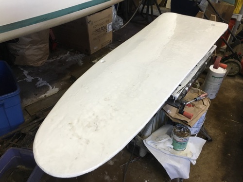
I took some measurements of the keel thickness and the clearance of the keel trunk. Now that I have added a layer of fiberglass the keel is about 1" thick at the top portion. The keel trunk is almost 1.6" wide. There is probably some taper to the keel trunk, since it is part of the hull mold, so I will have to try to get a measurement further up into the keel trunk. My guess, is that it is about 1.4" at the top.
Keel thickness at the top of the keel . . .

Keel trunk inside dimension at hull opening . . .

My plan is to add some 'pads' (sometimes referred to as 'pucks') near the trailing edge of the top portion of the keel. The thickness of the pucks need to be such that the overall dimension is a close fit to the inside dimension of the keel trunk, but still loose enough that the keel can swing up and down without causing interference or wear on the sides of the keel trunk.
Probably something like this . . .

Based on my approximations, the green line in the picture below would be where the keel protrudes from the hull in its lowered position, and the pads would be in the red outline area . . . each side of the keel.

The lateral movement of the keel would be confined to about 0.1" or maybe less , which should should help out both mechanically and in the handling of the boat.
The pads would be in the orange area shown in the profile diagram below. This would give the keel better mechanical support, rather than the current single point.

My plan is to build up the thickness of the keel in that area using the epoxy and fiberglass. My challenge will be to make sure I get a good fit of keel and keel trunk . . . not too tight and not too loose.


")