Volvo Penta V6-240 Fuel High Pressure Dropping to Zero

Biz603

Cadet
Joined
Sep 14, 2025
Messages
18
I'm pretty sure the HPFP is PWM with a fuel pump solenoid valve. The wires for it are in the harness and the diagram shows a HS and LS at the ECM. This thread has been a learning experience for me. Had no idea there was a pressure relief in the high pressure side, but it makes sense because this is a positive displacement liquid pump. It could blow itself up without relief. With the OPs symptoms it would sure be tops on the list, But 3 of them?

My manual has the fuel feed pump pressures showing.

Regulated Flow Rate 40 ± 2 GPH
Regulated Pressure @ Regulated Flow 60 ± 5 PSI
Max Static Pressure 86 PSI
Internal Regulated Pressure 10–40 PSI
High Pressure Pump Max Current @ Regulated Pressure 11.5 Amps
Low Pressure Pump Max Current @ Regulated Pressure 7.8 Amps

Are you seeing something different?
Learning much as well. More than I thought I would need for this fix.
I will check tomorrow and get back to you.
 

Biz603

Cadet
Joined
Sep 14, 2025
Messages
18
You maybe pulling back on the lever, but from these "snapshots" The ECM seems to be adding air and fuel.

If you look at manifold pressure, it's going up in chart 2 and has reached WOT in charts 3+4. Guessing the ECM is trying to add more air by opening the butterfly in the throttle body. If you look at TCP and TPS actual and commanded you might see more.

Now look at calculated fuel flow, It looks like the ECM is adding more and more fuel in charts 2+3 and even though it drops a bit in chart 4 it's still calling for more fuel then chart 1. If you look at injector pulse width you might see.

Hard to tell much with so little data. But (just a wild guess at this point) it looks a lot like there is air getting into the fuel system before the high pressure pump.

If you haven't yet, I would highly recommend that you take a look at cranking voltage during a Diacom recording session. Low voltage during cranking can cause some very weird things to happen in the ECM.
I have also found that once the engine gets into Closed Loop "CL+Adapt" take a look at how the fuel trims change thru out the RPMs and check the misfire counters both historic and real time.
Great points/suggestions.
Makes sense. I can hear what I think is the butterfly valve opening up while the RPM's are dropping off.
I will record and check the items you mentioned tomorrow. And the cracking voltage as well.
There is a braided fuel line from the second stage to the HPFP. I will check it for issues at the connecting ends. It has been in and out a few times now. Perhaps there is air getting in the system at one of the ends.

BTW - Thanks for sticking with me on this!! I appreciate it more than you know.
 
Last edited:

Biz603

Cadet
Joined
Sep 14, 2025
Messages
18
Ok Muc, I have some test results for you.
Watching the voltage at startup. The battery is at 12.1VDC before cranking.
During cranking it drops to 9.4 for a fraction of a second then comes back up to 14.2 when the alternator kicks in and the engine starts, about 2 seconds later.

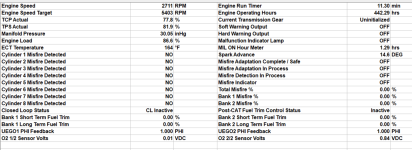
In terms of misfires. Didn't see any recorded. Here's a screen shot after ramping up to 5400 (surprised) just after the engine quit.
1758497722132.png

As for fuel trims, they hover around +/-4. Never above 9. Always seem to hunt back to around zero in with a steady throttle position.

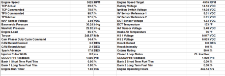
You were right about the The TCP and TPS actual and commanded numbers are tight throughout the RPM range. Until the RPM start to drop, because of this issue, then the TPS commanded and actual go to near 100%. TCP stays where it is.
You can see it here, taken just after failure:
1758498749965.png

For what it's worth, the Engine Load Data will jump to 86% during the failure. I believe this number is calculated off the throttle position, MAP, and other sensors. Since it's calling for more air and fuel it seems to make sense it's going up. Again, sounds like the butterfly valve is opening all the way during failure.

Regarding the fuel pressures / flow. I don't know of a good way to measure the flows, but I can tell you stage 1 sits around 20psi. Stage 2 stays around 70-75 psi. Both never really move or drop. At any RPM, during a failure, or after a failure.

What do you think?

If it's air coming in the fuel line, wouldn't gas leak out those same holes while under pressure?

I wonder if there is a way to determine if the relief valve is opening up?

Thanks again for the continued support.
 

harringtondav

Commander
Joined
May 26, 2018
Messages
2,488
I'm pretty sure the HPFP is PWM with a fuel pump solenoid valve. The wires for it are in the harness and the diagram shows a HS and LS at the ECM. This thread has been a learning experience for me. Had no idea there was a pressure relief in the high pressure side, but it makes sense because this is a positive displacement liquid pump. It could blow itself up without relief. With the OPs symptoms it would sure be tops on the list, But 3 of them?

My manual has the fuel feed pump pressures showing.

Regulated Flow Rate 40 ± 2 GPH
Regulated Pressure @ Regulated Flow 60 ± 5 PSI
Max Static Pressure 86 PSI
Internal Regulated Pressure 10–40 PSI
High Pressure Pump Max Current @ Regulated Pressure 11.5 Amps
Low Pressure Pump Max Current @ Regulated Pressure 7.8 Amps

Are you seeing something different?
I'm seeing the same data.
I took a closer look at the engine workshop manual and sure enough, a connector is shown on the rear of the HPFP. Also spent time studying the ECM wiring. Each rail has a connector, and per the OP the starboard gets a signal from the ECM for fuel pressure.
I got bleary eyed tracing the wires to these two harnesses. Most are for low and high injector pressures. I don't know if the HPFP is wired for a relief solenoid. It looks pretty compact. My guess is the ECM de-strokes the pump to adjust pressures. DTC 0088 indicates a rail pressure > 10 bar/133 psi over the rpm requirement and derates. OP didn't report this DTC.
I'm stumped. Other than a faulty pressure sensor, I don't know what other conditions would cause the ECM to drop rail pressure.
 

muc

"Retired" Association of Marine Technicians...
Joined
Jul 7, 2004
Messages
2,281
It would have been nice if there was an issue with the fuel feed pump, it would fit so nice with the symptoms. But your testing rules that out.

Might be better if you posted the .rec files. the two you just posted are just a snapshot of a moment in time. I can't see much in them.

The first chart of the misfires shows nothing because misfire detection isn't on at this moment in time. Did you look in the system info tab? Scroll down to the bottom.
For the different features of this engine to work, certain parameters need to be met first. I don't have enough hands on time with these DI engines to know what those parameters are. This is why I recommend a long 20-30 minutes .rec file. spend about 5 minutes at 1500,2500,3500,4500 and WOT.

The second chart was done before the engine was up to full temp, this can skew any readings. But I do see injector on time at 0 ms. Wondering why that is? It might be good to do a .rec file while running the injector monitor.

Cranking voltage at the ECM of 9.6 is low. How many batteries, what MCA rating and how old are they? The last dealer I worked at refused to troubleshoot newer engines unless they had a correctly rated, less then 3 year old battery.

The air in the system is more a comment on my part. It just fits the symptom. I have not idea how it could actually happen with your system.

I don't know of any way to test the relief. The only way I can think of is to replace it, but You've already done that twice!

I don't know what to think at this point. Maybe some good .rec files would show something?
 

muc

"Retired" Association of Marine Technicians...
Joined
Jul 7, 2004
Messages
2,281
I'm seeing the same data.
I took a closer look at the engine workshop manual and sure enough, a connector is shown on the rear of the HPFP. Also spent time studying the ECM wiring. Each rail has a connector, and per the OP the starboard gets a signal from the ECM for fuel pressure.
I got bleary eyed tracing the wires to these two harnesses. Most are for low and high injector pressures. I don't know if the HPFP is wired for a relief solenoid. It looks pretty compact. My guess is the ECM de-strokes the pump to adjust pressures. DTC 0088 indicates a rail pressure > 10 bar/133 psi over the rpm requirement and derates. OP didn't report this DTC.
I'm stumped. Other than a faulty pressure sensor, I don't know what other conditions would cause the ECM to drop rail pressure.
I just brought up the DTC 0088 because it's the only place the fuel control solenoid is mentioned. I found it somewhat strange that it wasn't listed as a possibility for a low pressure DTC. Maybe Volvo feels it can't fail that way? The low pressure DTC only sets at a very low pressure.

Each injector gets a low side and high side connection to the ECM. Guessing low is negative and high is positive voltage. What I don't know is if either of these are being regulated. This is different from other EFI systems I'm used to. Why GM did it this way instead of supplying batt volts to one side and grounding the other, I don't know.

I think the fuel control solenoid restricts the flow into the HPP. The pump is mechanically driven by the cam, I would think it would be pretty difficult to adjust the stroke.

I haven't been to school for these DI engines, nor do I have access to the "design and function" manual. So I don't know if a faulty pressure sensor could cause this problem. I have been burned to many times with brand new factory parts being bad out of the box, so I really hate to just swap new parts. But if you don't have access to a known good running engine to swap with --- don't have any choice.
 

harringtondav

Commander
Joined
May 26, 2018
Messages
2,488
Ok Muc, I have some test results for you.
Watching the voltage at startup. The battery is at 12.1VDC before cranking.
During cranking it drops to 9.4 for a fraction of a second then comes back up to 14.2 when the alternator kicks in and the engine starts, about 2 seconds later.

In terms of misfires. Didn't see any recorded. Here's a screen shot after ramping up to 5400 (surprised) just after the engine quit.
View attachment 411782

As for fuel trims, they hover around +/-4. Never above 9. Always seem to hunt back to around zero in with a steady throttle position.

You were right about the The TCP and TPS actual and commanded numbers are tight throughout the RPM range. Until the RPM start to drop, because of this issue, then the TPS commanded and actual go to near 100%. TCP stays where it is.
You can see it here, taken just after failure:
View attachment 411783

For what it's worth, the Engine Load Data will jump to 86% during the failure. I believe this number is calculated off the throttle position, MAP, and other sensors. Since it's calling for more air and fuel it seems to make sense it's going up. Again, sounds like the butterfly valve is opening all the way during failure.

Regarding the fuel pressures / flow. I don't know of a good way to measure the flows, but I can tell you stage 1 sits around 20psi. Stage 2 stays around 70-75 psi. Both never really move or drop. At any RPM, during a failure, or after a failure.

What do you think?

If it's air coming in the fuel line, wouldn't gas leak out those same holes while under pressure?

I wonder if there is a way to determine if the relief valve is opening up?

Thanks again for the continued support.
Still digesting what I've learned from you and @muc.
HPFP is PWM.
Earler this summer I was chasing a performance problem on my G5 250 hp engne. Muc suggested my low cranking voltage, similar to yours, could be messing with the ECM initialization. I replaced my four year old battery and saw some improvement.
Based on your new supply pump and HPFP pumps I think its safe to assume these are good. So it seems some other inputs or conditions are causing the ECM to derate.
Your Diacom charts seem to point to a disconnect between TPC and TPS actual and commanded values. Your comment about the TB gasping at shut down caught my eye.
Take a look at your ECG diagnostics manual. I did a search for "body" and came to page 87 for a good description of throttle body operation and one related DTC. There are two others with their own DTC. Derate2 can occur with each.
You haven't reported any of these DTCs, but it may be a factor with your issue.
 

Biz603

Cadet
Joined
Sep 14, 2025
Messages
18
I'm seeing the same data.
I took a closer look at the engine workshop manual and sure enough, a connector is shown on the rear of the HPFP. Also spent time studying the ECM wiring. Each rail has a connector, and per the OP the starboard gets a signal from the ECM for fuel pressure.
I got bleary eyed tracing the wires to these two harnesses. Most are for low and high injector pressures. I don't know if the HPFP is wired for a relief solenoid. It looks pretty compact. My guess is the ECM de-strokes the pump to adjust pressures. DTC 0088 indicates a rail pressure > 10 bar/133 psi over the rpm requirement and derates. OP didn't report this DTC.
I'm stumped. Other than a faulty pressure sensor, I don't know what other conditions would cause the ECM to drop rail pressure.
Thanks for the reply. The HPFP is not wired for a relief valve. The internal relief valve seems to be just mechanical and set at the factory. No set screws to change it, anywhere.

There are only two wires going to the HPFP and they, as you said, are used to control the pressure the HPFP is putting out. And my pressures vs RPM are running as the chart above suggests and I have no codes, so I'm thinking the HPFP signal from the ECM and the pressure sensor are good.

How can I tell if the ECM is dropping the pressure vs the relief valve opening?
Anyone know where the fuel goes when the relief opens?
I've had someone suggest it goes into the crankcase?
How do I tell if I have gas in my crankcase?
I can pull the dip stick. Not sure I'd smell it.

Again, this is my third HPFP doing the same thing. But I'm keeping an open mind.
 
Last edited:

Biz603

Cadet
Joined
Sep 14, 2025
Messages
18
It would have been nice if there was an issue with the fuel feed pump, it would fit so nice with the symptoms. But your testing rules that out.

Might be better if you posted the .rec files. the two you just posted are just a snapshot of a moment in time. I can't see much in them.

The first chart of the misfires shows nothing because misfire detection isn't on at this moment in time. Did you look in the system info tab? Scroll down to the bottom.
For the different features of this engine to work, certain parameters need to be met first. I don't have enough hands on time with these DI engines to know what those parameters are. This is why I recommend a long 20-30 minutes .rec file. spend about 5 minutes at 1500,2500,3500,4500 and WOT.

The second chart was done before the engine was up to full temp, this can skew any readings. But I do see injector on time at 0 ms. Wondering why that is? It might be good to do a .rec file while running the injector monitor.

Cranking voltage at the ECM of 9.6 is low. How many batteries, what MCA rating and how old are they? The last dealer I worked at refused to troubleshoot newer engines unless they had a correctly rated, less then 3 year old battery.

The air in the system is more a comment on my part. It just fits the symptom. I have not idea how it could actually happen with your system.

I don't know of any way to test the relief. The only way I can think of is to replace it, but You've already done that twice!

I don't know what to think at this point. Maybe some good .rec files would show something?
I've attached some .rec files. Not all are up to temp. But some are slow rpm increases and holds until fail. Other are ramps to fail. And one is for the misfire data.
Can do a longer run and get you that .rec file late tomorrow.
Didn't look at the system tab, but can do.
The battery is 3 years old and AGM type. It's kept on a trickle charger all winter. I'll try a new one because I'm desperate, and get back to you.
 

Biz603

Cadet
Joined
Sep 14, 2025
Messages
18
Still digesting what I've learned from you and @muc.
HPFP is PWM.
Earler this summer I was chasing a performance problem on my G5 250 hp engne. Muc suggested my low cranking voltage, similar to yours, could be messing with the ECM initialization. I replaced my four year old battery and saw some improvement.
Based on your new supply pump and HPFP pumps I think its safe to assume these are good. So it seems some other inputs or conditions are causing the ECM to derate.
Your Diacom charts seem to point to a disconnect between TPC and TPS actual and commanded values. Your comment about the TB gasping at shut down caught my eye.
Take a look at your ECG diagnostics manual. I did a search for "body" and came to page 87 for a good description of throttle body operation and one related DTC. There are two others with their own DTC. Derate2 can occur with each.
You haven't reported any of these DTCs, but it may be a factor with your issue.
I will replace the battery tomorrow and try it.
My page number is different but the description was there. It seems that the throttle body commanded position changes based on "Engine RPM, engine load via the MAP sensor" data.
So as this failure is happening, the RPMs are going down and the Engine Load is going up. All reasons to command the butterfly to open. Seems to make sense that what I hear.
 

harringtondav

Commander
Joined
May 26, 2018
Messages
2,488
How can I tell if the ECM is dropping the pressure vs the relief valve opening?
Anyone know where the fuel goes when the relief opens?
I've had someone suggest it goes into the crankcase?
How do I tell if I have gas in my crankcase?
I can pull the dip stick. Not sure I'd smell it.
I'm air grabbing here.
I suspect the high pressure relief fuel goes back into the fuel supply port's line against its 65 psi max pressure. The diagnostic manual states the supply pump is PWM to regulate its pressure, so I assume it would back off to compensate. ....haven't seen this on with wiring diagrams. ...dumping gas back into the crankcase intentionally violates any design stds I've known.
As far as why the high pressure drops is the million $ question. Some ECM input is causing this. I've mentioned a faulty rail pressure sensor, but don't want to encourage more expensive part swapping.
I did a PDF search in the diagnostic manual for "derate" and found many input conditions that would cause this. Many are discrepancies in sensor voltages. My best advice is to note these and run more Diacom records. The graphing tool has a list of all monitored inputs. You can graph three at a time, and re-graph from the same recording.
Needle in a haystack search.
 

Biz603

Cadet
Joined
Sep 14, 2025
Messages
18
I just brought up the DTC 0088 because it's the only place the fuel control solenoid is mentioned. I found it somewhat strange that it wasn't listed as a possibility for a low pressure DTC. Maybe Volvo feels it can't fail that way? The low pressure DTC only sets at a very low pressure.

Each injector gets a low side and high side connection to the ECM. Guessing low is negative and high is positive voltage. What I don't know is if either of these are being regulated. This is different from other EFI systems I'm used to. Why GM did it this way instead of supplying batt volts to one side and grounding the other, I don't know.

I think the fuel control solenoid restricts the flow into the HPP. The pump is mechanically driven by the cam, I would think it would be pretty difficult to adjust the stroke.

I haven't been to school for these DI engines, nor do I have access to the "design and function" manual. So I don't know if a faulty pressure sensor could cause this problem. I have been burned to many times with brand new factory parts being bad out of the box, so I really hate to just swap new parts. But if you don't have access to a known good running engine to swap with --- don't have any choice.
I would think that when it fails I'd get a DTC 0087. But I don't.
I'm open to trying another new HPFP. It means replacing the high pressure fuel pipes again, but I am getting desperate.
If we can't find the issue by this weekend, I'll order another one and install it.
 

Biz603

Cadet
Joined
Sep 14, 2025
Messages
18
I'm air grabbing here.
I suspect the high pressure relief fuel goes back into the fuel supply port's line against its 65 psi max pressure. The diagnostic manual states the supply pump is PWM to regulate its pressure, so I assume it would back off to compensate. ....haven't seen this on with wiring diagrams. ...dumping gas back into the crankcase intentionally violates any design stds I've known.
As far as why the high pressure drops is the million $ question. Some ECM input is causing this. I've mentioned a faulty rail pressure sensor, but don't want to encourage more expensive part swapping.
I did a PDF search in the diagnostic manual for "derate" and found many input conditions that would cause this. Many are discrepancies in sensor voltages. My best advice is to note these and run more Diacom records. The graphing tool has a list of all monitored inputs. You can graph three at a time, and re-graph from the same recording.
Needle in a haystack search.
Yah, this one is very illusive.
I've swapped the ECT and oil pressure sensors. I think there are 6-7 sensors that are used to calculate the ECM output to the HPFP. Happy to swap more.
I dumped some .rec files in one of the posts below if you want a look at the other sensors. They seem ok, but I might be missing something.
I'll run some more .rec, at temp and different RPMs and post them tomorrow, if I can.
 

muc

"Retired" Association of Marine Technicians...
Joined
Jul 7, 2004
Messages
2,281
How can I tell if the ECM is dropping the pressure vs the relief valve opening?
Anyone know where the fuel goes when the relief opens?
I've had someone suggest it goes into the crankcase?
How do I tell if I have gas in my crankcase?
I can pull the dip stick. Not sure I'd smell it.
Only way I can think of is to monitor the PWM with a scope.
Guessing it just goes back to HPFP inlet.
If it leaks past the pump piston. I think this is unlikely.
Yes you would smell it. Not at the dipstick unless you first blow down the tube to clear the oil that just sits there, open the oil fill and smell there.
 

muc

"Retired" Association of Marine Technicians...
Joined
Jul 7, 2004
Messages
2,281
I've attached some .rec files. Not all are up to temp. But some are slow rpm increases and holds until fail. Other are ramps to fail. And one is for the misfire data.
Can do a longer run and get you that .rec file late tomorrow.
Didn't look at the system tab, but can do.
The battery is 3 years old and AGM type. It's kept on a trickle charger all winter. I'll try a new one because I'm desperate, and get back to you.
I don't see any .rec files.
Your battery had a resting voltage of 12.1v this indicates a battery with about 50% charge. Cranking dropped that to 9.4v. 9.6v is considered bare minimum. I don't know if the battery you have now is causing or contributing to your current problems, but it can't be helping.

Here is the bare minimum from Volvo;
12 volt 650 Cold Cranking Amps (CCA) 135 minute reserve capacity
NOTICE! Do not use deep cycle batteries to start the engine. A deep cycle battery, while it may have enough CCAs, may not have enough voltage during cranking to power the engine computer (ECM). This can cause problems with the ECM and engine.

I recommend a minimum 1000 marine cranking amps (MCA), 800 cold cranking amps (CCA), or 180 ampere hour (Ah) marine starting battery.
 

muc

"Retired" Association of Marine Technicians...
Joined
Jul 7, 2004
Messages
2,281
Some ECM input is causing this.
I don't agree. Could be a ECM driver output. Could even be something fuel related. I have seen a rubber fuel line that had a little flap of rubber come loose inside. At low fuel flow rates, everything was fine. But once the flow increased enough that flap would move and restrict the flow enough to cause issues.
 

muc

"Retired" Association of Marine Technicians...
Joined
Jul 7, 2004
Messages
2,281
I would think that when it fails I'd get a DTC 0087. But I don't.
I'm open to trying another new HPFP. It means replacing the high pressure fuel pipes again, but I am getting desperate.
If we can't find the issue by this weekend, I'll order another one and install it.
DTC 0087
Data valid but pressure below 20 PSI (1.37 BAR) for more than 3
seconds

Why Volvo picked below 20 PSI to set this code I have no idea. I doubt 20 PSI is even enough to idle this engine. But that's what they chose so unless the ECM sees below 20 PSI for more than 3 seconds ---- no code set.

If you have been buying Genuine Volvo pumps, I don't think another one will help.
 

muc

"Retired" Association of Marine Technicians...
Joined
Jul 7, 2004
Messages
2,281
Earlier I saw a bit of discussion about TCP TSP actual and commanded. Because trouble shooting odd issues like this usually requires understanding how and why the ECM makes the decisions it does, here is a little explanation. ETC = electronic throttle control, "fly by wire"

The Speed Based Throttle control system is used on all –J and later ETC engines not equipped with EVC-ec. In the speed based throttle system the TCP is still the driver’s “throttle request” and is still “hardwired” to the ECM. What’s different is that with this system the ECM sees the “TCP Actual %” and converts that percentage to a “target engine speed”. The ECM then controls the throttle blade to either increase or decrease engine speed until the engine speed (from the CKP sensor) indicates that it has reached the target. This occurs anytime the engine is not in idle mode. If the TCP is advanced to 100%, the target engine
speed is set to approximately 100 RPM higher than the maximum rated speed for that engine.
To the customer, this speed based system causes the engine to seem to operate differently than ETC engines in the past because the engine is governed to an engine speed not a lever or throttle blade position. As an example: the boat is cruising at 3000 rpm and the driver doesn’t move the helm lever but he starts turning to port. This will cause an increase in load on the engine. In the past and with lever based systems, the engine would start to slow down due to the increased load and the driver would have to add more throttle to maintain the same engine speed. With a speed based system as the driver makes the turn, he did not move the helm lever so the “target engine speed” did NOT change. So as he makes the turn, engine load increases, rpm starts to drop below the target so the ECM opens the throttle to try to maintain the target engine speed.
Likewise; if the boat is cruising and the drive is under-trimmed (bow down), as the driver trims the bow up, engine speed will NOT increase. Boat speed will increase. If the driver continues to trim the drive up, the load on the engine will decrease and the ECM will not need to open the throttle blade as far as it was to maintain the target engine speed. As the driver continues to over-trim the drive (bow up), the boat will also start to slow down but engine speed will not
change.

So the only thing the ECM is looking at (for this feature) is RPM.

But I don't think I've seen what model or serial number engine @Biz603 has posted anywhere. Just been assuming it's not a EVC equipped engine. Might be good to post that info, it could change things.
 

Lpgc

Petty Officer 1st Class
Joined
Jun 17, 2023
Messages
323
I've never used OBD equipment on a marine engine but I diagnose vehicle engine problems everyday. On a car P0174 would point to lean mixture on bank2, on this boat engine the 0174 code also seems to point to lean mixture on bank2. The way it detects mixture is using an O2 sensor, the boat engine seems to have O2 sensors because the OBD information includes readings for mixture.

If the O2 sensor on bank2 were bad that could maybe account for the engine going into limp mode? In both 'OBD snapshot' tables posted by @Biz603 in post #24 closed loop fuelling is disabled and the 'readings' from the O2 sensors seem unlikely to be correct because they point to an absolutely correct air fuel ratio. In practice the air fuel ratio usually flutters around 1 (where 1 is correct, above 1 usually lean, below 1 usually rich) so we might expect to see numbers like 0.997, 1.002 etc. At high engine load the engine normally gets a rich mixture so the reading is usually below 1, on a car it might go to 0.9 (you could read that as 10% rich). A lot of OBD systems on cars will create fake numbers for components they have deemed to be not working properly, they might give an A/F reading of 1 pointing to absolutely correct mixture for a failed O2 sensor.

Summing up, I'm suggesting the O2 / lambda sensor on cylinder bank 2 could be at fault...
 
Top